Technique for reducing pole tip protrusion in a magnetic write head and GMR stripe temperature in an associated read head structure utilizing one or more internal diffuser regions

Active Publication Date: 2005-05-17
WESTERN DIGITAL TECH INC
View PDF4 Cites 156 Cited by
  • Summary
  • Abstract
  • Description
  • Claims
  • Application Information

AI Technical Summary

Benefits of technology

[0012]Through the use of the exemplary technique disclosed, PTP is significantly reduced as both gold and copper are very conductive materials. As a result, they are able to conduct away the heat generated by the current in the coils, photoresist, poles and shields. This results in a lower overall head temperature thereby minimizing thermal expansion and pole tip pro

Problems solved by technology

Moving significantly in any direction away from a “one” causes a dramatic loss of magnetic field strength.
In use, the differential wear properties of these materials can cause the pole pieces to effectively recede from the air bearing surface (“ABS”) resulting in what is known as pole tip recession (“PTR”).
This undesired phenomena causes an increased spacing of the write head from the storage m

Method used


Image

  • Technique for reducing pole tip protrusion in a magnetic write head and GMR stripe temperature in an associated read head structure utilizing one or more internal diffuser regions
  • Technique for reducing pole tip protrusion in a magnetic write head and GMR stripe temperature in an associated read head structure utilizing one or more internal diffuser regions
  • Technique for reducing pole tip protrusion in a magnetic write head and GMR stripe temperature in an associated read head structure utilizing one or more internal diffuser regions

Examples


Embodiment Construction

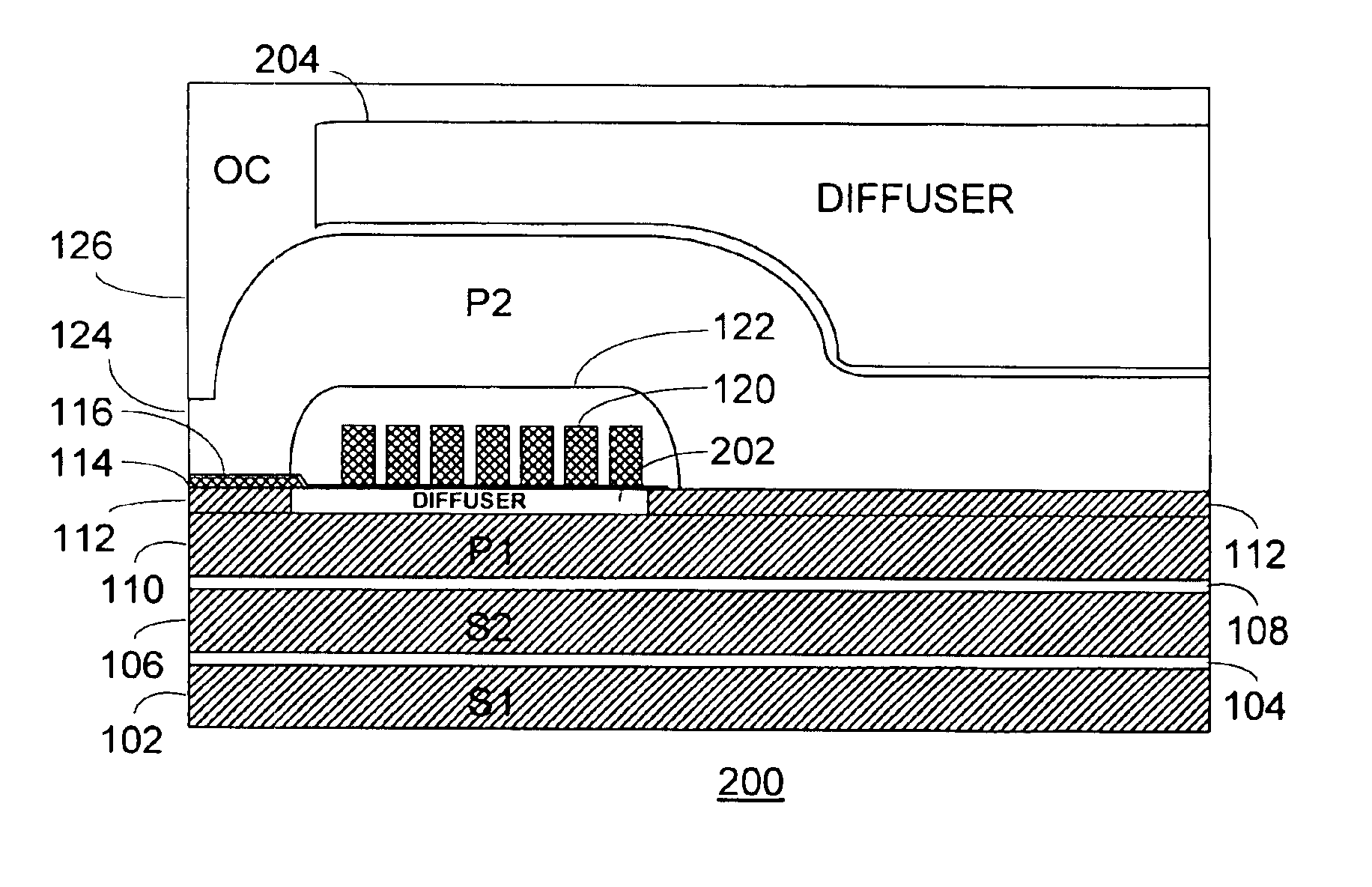
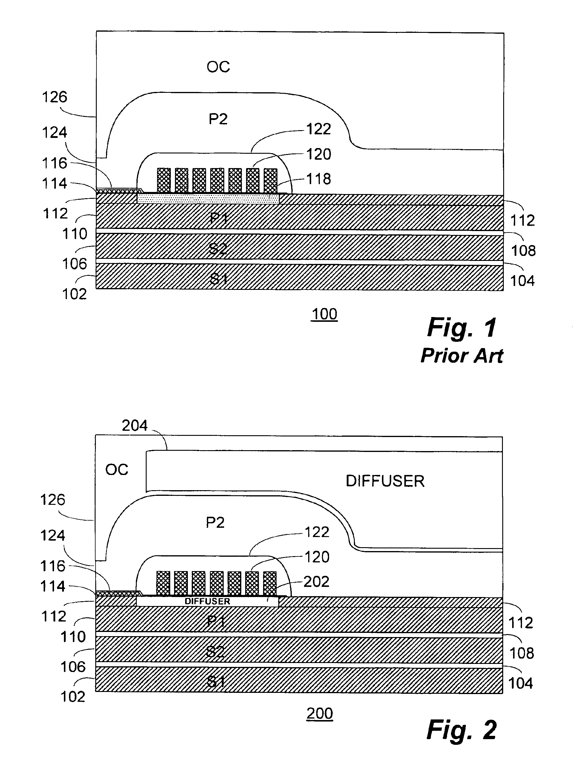
[0020]With reference now to FIG. 1, a simplified cross-sectional view of a portion of a conventional inductive write head 100 is shown. The write head 100 may form one part of a “merged-head” or “shared shield” transducer structure in conjunction with a magnetoresistive (“MR”), GMR or other read head (not shown).

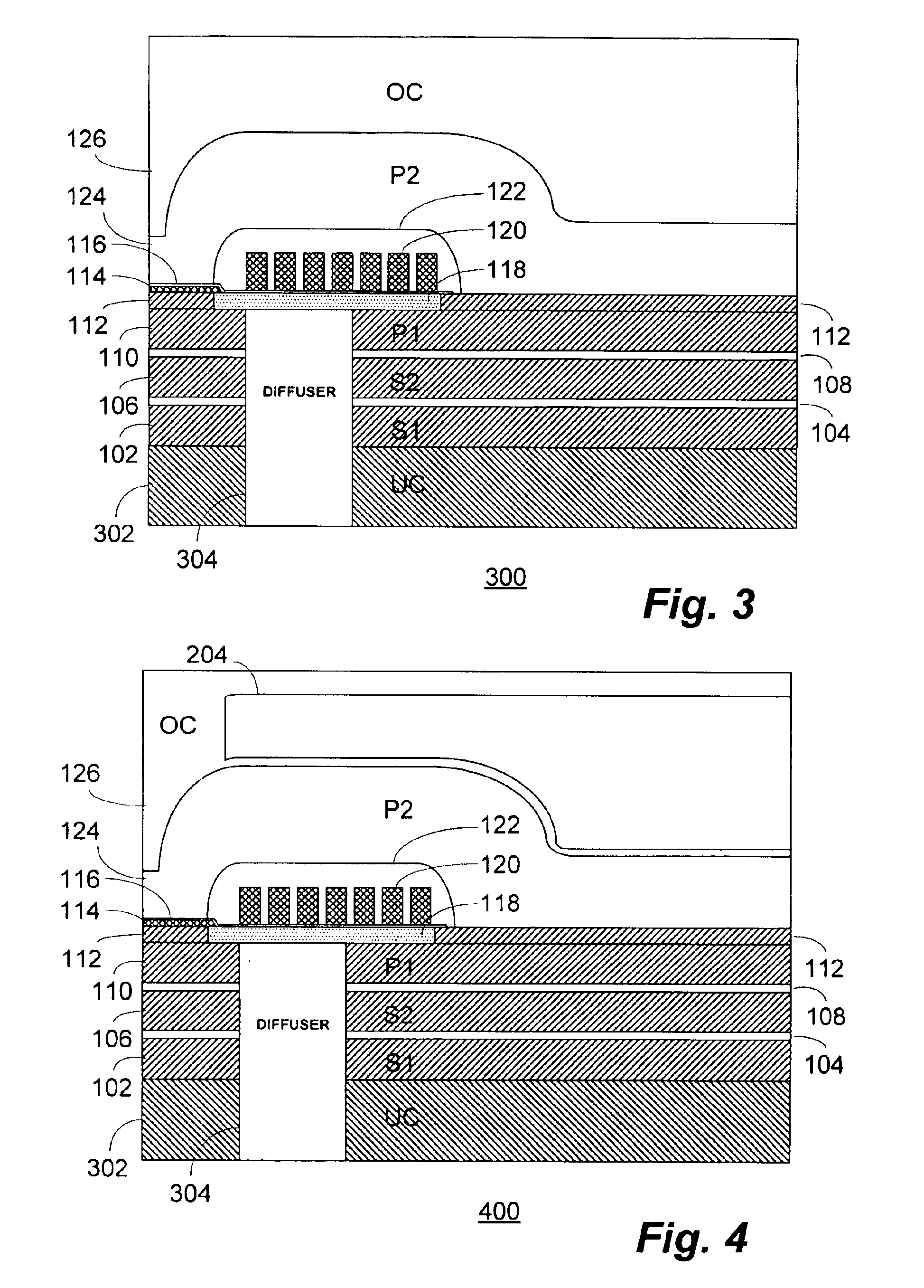
[0021]The write head 100 comprises, in pertinent part, a first shield layer (“S1”) 102 which may be formed, for example on an undercoat layer (not shown) of the overall transducer structure. A reader gap layer 104 is intermediate the first shield layer 102 and a second shield layer (“S2”) 106. A piggyback gap layer 108 separates the second shield layer 106 from the first pole (“P1”) 110. The first and second shield layers 102, 106 may be formed, for example, of permalloy and be between 1.5 and 2.0 microns in thickness.

[0022]A pedestal layer 112 is formed overlying the first pole 110 and is patterned to form the pedestal shown adjoining the air bearing surface of the write he...


PUM


Abstract

A technique for reducing pole tip protrusion (“PTP”) in a magnetic write head and giant magnetoresistive (“GMR”) stripe temperature in an associated read head structure utilizing one or more internal diffuser regions. In a representative embodiment disclosed, this may be effectuated through the appropriate placement of a relatively highly conductive material diffuser region (e.g. gold (Au) or copper (Cu)) above the poles, between the first pole and the coil and/or through the first pole, second and first shields and undercoat layer to the substrate in order to conduct heat away from the write head poles, insulating layers (e.g. photoresist) and shields.

Description

BACKGROUND OF THE INVENTION[0001]The present invention relates, in general, to the field of magnetic recording heads. More particularly, the present invention relates to a technique for reducing pole tip protrusion (“PTP”) in a magnetic write head and giant magnetoresistive (“GMR”) stripe temperature in an associated read head structure utilizing one or more internal diffuser regions.[0002]Recording heads are miniature components (with dimensions of on the order of about 1 mm2) that read and write information to and from a hard-drive disk or another storage medium. When writing, the head acts as a small electromagnet wherein positive and negative pulses of current are translated into north and south magnetic poles on a rotating magnetic disk. When reading, the head senses magnetic fields from these poles and translates the alternating fields into positive and negative voltage pulses. These pulses become the bits of digital information stored on the disk. A recording head is generall...

Claims


Application Information

Patent Timeline
IPC IPC(8): G11B5/31G11B5/00G11B5/39
CPCB82Y10/00B82Y25/00G11B5/313G11B5/3136G11B5/3133G11B5/3106G11B2005/3996G11B5/3903G11B5/3967G11B2005/0016
Inventor ALFOQAHA, ARSHADFANSLAU, EDMUND
Owner WESTERN DIGITAL TECH INC
Why Eureka
Try Eureka