Image forming apparatus having reduced power consumption mode and control method therefor

a technology of power consumption mode and image forming apparatus, which is applied in the direction of electrographic process apparatus, instruments, optics, etc., can solve the problems of the above-mentioned network system according to the prior art, and achieve the effect of reducing power consumption mod

Active Publication Date: 2005-05-17
CANON KK
View PDF4 Cites 34 Cited by
  • Summary
  • Abstract
  • Description
  • Claims
  • Application Information

AI Technical Summary

Benefits of technology

[0012]It is a first object of the present invention to provide an image forming apparatus having a reduced power consumption mode and a control method therefor, which have solved the above described problem.

Problems solved by technology

However, the above described network system according to the prior art suffers from the following problem:
Therefore, even though the copying machine is in the sleep state where energy conservation is being achieved, it is necessary to supply electric power to the entire copying machine whenever the status of the copying machine is inquired, or alternatively, the copying machine needs to constantly hold all the engines in energized states without shifting to the sleep mode, which is contradictory to the recent trend toward energy conservation.

Method used


Image

  • Image forming apparatus having reduced power consumption mode and control method therefor
  • Image forming apparatus having reduced power consumption mode and control method therefor
  • Image forming apparatus having reduced power consumption mode and control method therefor

Examples


first embodiment

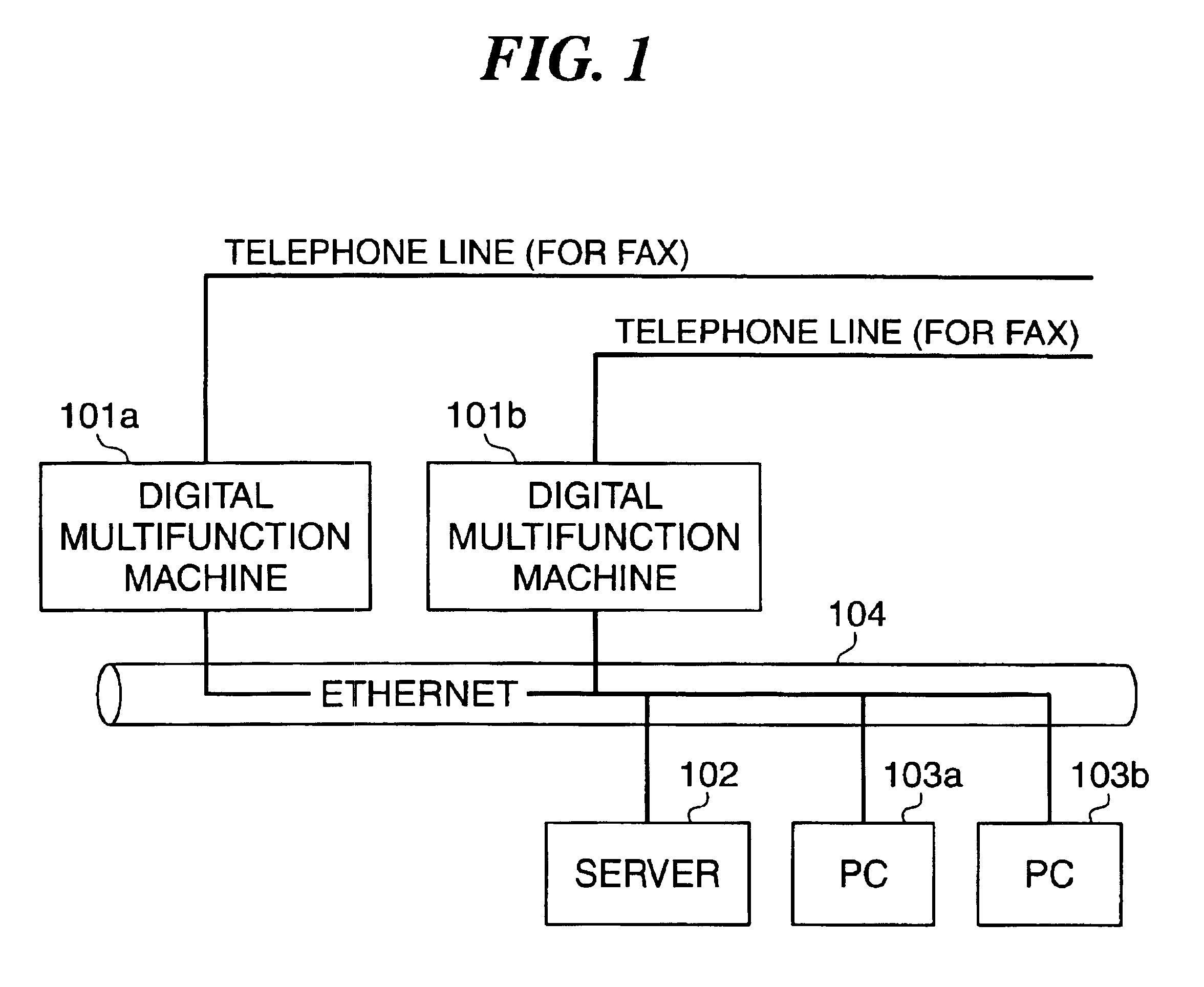
[0053]FIG. 1 is a block diagram showing an example of the configuration of a network system to which to which is applied an image forming apparatus according to the present invention. Needless to say, the image forming apparatus according to the present invention include printing apparatuses (printers) using the electrophotographic printing method, the ink jet printing method, and other printing methods, facsimile machines or digital multifunction machines for performing multiple function image forming processing, including print processing and facsimile processing. Hereinafter, a description will be given of digital multifunction machines by way of example.

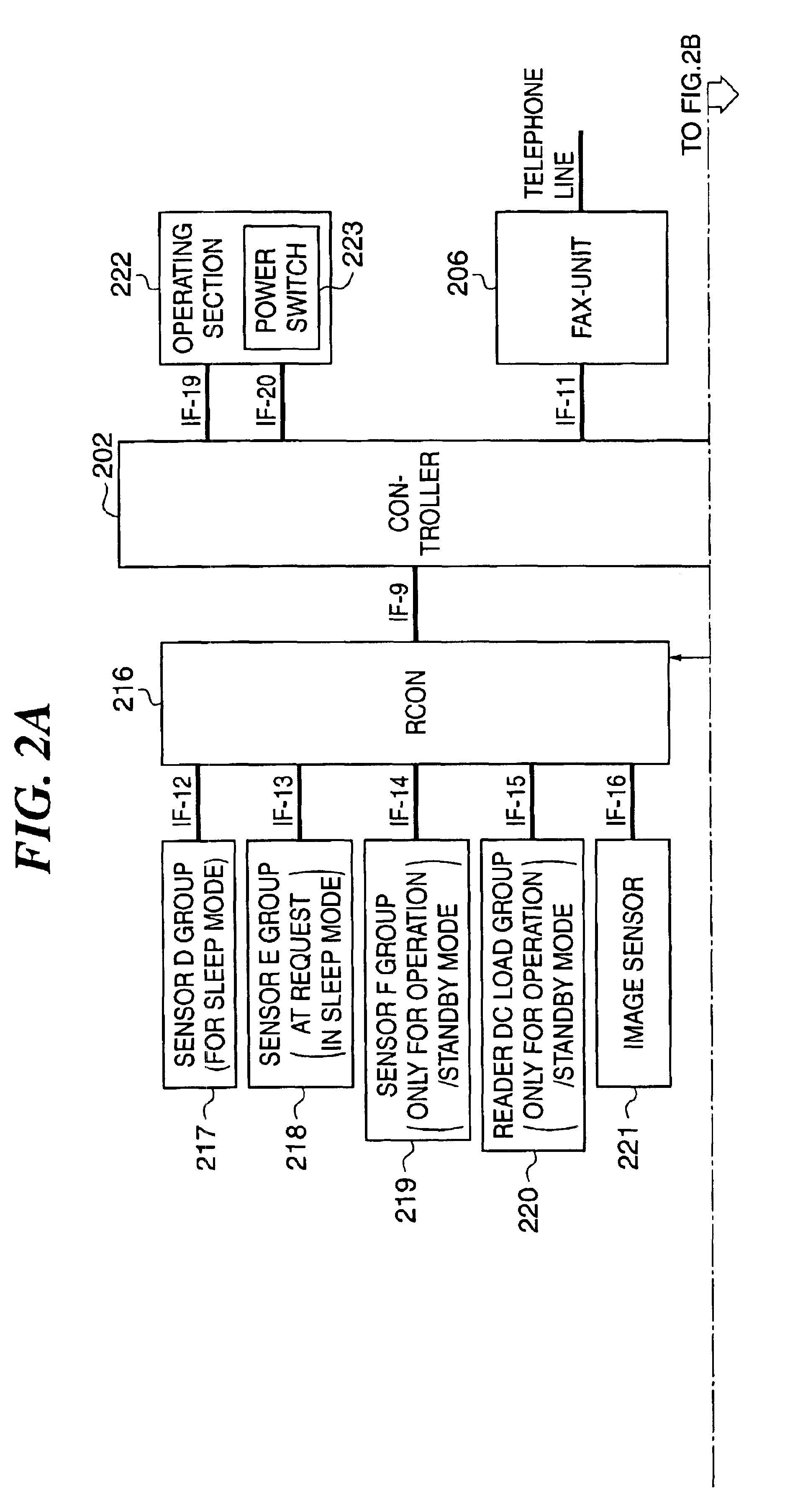
[0054]In FIG. 1, reference numerals 101a and 101b designate digital multifunction machines, each of which is operated by electric power supplied to a printer section (DCON) 201, a reader section (RCON) 216, and a controller 202 thereof, from a DC power supply 203, as described in detail hereinafter.

[0055]Reference numeral 102 des...

second embodiment

[0224]Next, the present invention will be described.

[0225]The second embodiment is distinguished from the above described first embodiment in which when the image forming apparatus (digital multifunction machine 101a (101b)) receives a status request from an external device via the network during the sleep mode, the sub CPU (1-chip microcomputer Q702) transmits status information to the external device in place of the main CPU (main-chip microcomputer Q701), in that only when there is any change in the status during the sleep mode, the sub CPU transmits status information to an agency server (server 101), and a status request received via the network by the image forming apparatus is responded to not by the sub CPU, but by the agency server 102.

[0226]FIG. 15 is a block diagram showing details of the arrangement of a controller and its related parts of an image forming apparatus according to the second embodiment. Component parts and signals corresponding to those in FIG. 7 are desig...

third embodiment

[0295]Next, the present invention will be described.

[0296]Although in the above described first and second embodiments, the sub CPU (1-chip microcomputer Q702) and the main CPU (main-chip microcomputer Q701) are physically separate from each other, this is not limitative. In the present embodiment, a single chip (CPU) is operated with a high-frequency clock in the normal mode, and operated with a low-frequency clock in the energy-saving mode. Further, in the energy-saving mode, a local power supply in the single chip is saved, and the chip is driven with small power consumption.

[0297]The present invention includes a combination of the above described embodiments.

[0298]Hereafter, a description will be given of a data processing program that can be read by the image forming apparatus according to any one of the above described embodiments, by referring to a memory map shown in FIG. 23.

[0299]FIG. 23 is a diagram showing the structure of a memory map of a storage medium that stores vari...


PUM


Abstract

There is provided an image forming apparatus which is capable of responding to a status request with the minimum possible energy consumption even when the image forming apparatus is in a sleep state, to thereby achieve energy conservation. A main-chip microcomputer Q701 responds to an externally input status request when the image forming apparatus is in a normal standby mode, and enters an inoperative state where it does not respond to the externally input status request when the image forming apparatus is in a reduced power consumption mode. A 1-chip microcomputer Q702 responds to the externally input status request on behalf of the main-chip microcomputer Q701 when the image forming apparatus is in the reduced power consumption mode.

Description

BACKGROUND OF THE INVENTION[0001]1. Field of the Invention[0002]The present invention relates to an image forming apparatus having a reduced power consumption mode in which power consumption is maintained at a lower level than in a normal standby state, and a control method of controlling an image forming apparatus of this type.[0003]2. Description of the Related Art[0004]Conventionally, there exists a system in which image forming apparatuses, such as printers, copying machines, and multifunction machines, and computers are interconnected through a network.[0005]FIG. 24 is a block diagram showing an example of the configuration of a conventional network system including conventional image forming apparatuses, which is used by a plurality of users under a network environment, for example.[0006]In FIG. 24, the network system is comprised of a plurality of personal computers PC 1103a, PC 1103b, copying machines 1101a, 1101b, and a server 1102, which are interconnected through a networ...

Claims


Application Information

Patent Timeline
Patent Type & Authority Patents(United States)
IPC IPC(8): G03G15/00
CPCG03G15/5004G03G15/5083G03G2215/00109
Inventor UCHIZONO, TAKEHARUMIYAMOTO, KAZUKIMIURA, SHIGEOUSHIRO, TAKAHIROTAKEDA, TOMOYUKITAKATA, SHINICHI
Owner CANON KK
Why Eureka
Try Eureka