
Switch matrix packaging for high availability

a switch matrix and high availability technology, applied in the field of high availability system for cable network, can solve the problems of difficult installation and replacement of cables, limited space for connection points, and high cost of cable replacement, so as to facilitate rapid replacement of faulty cables or network components, increase the access to cable connection points, and increase the view of connection points

Inactive Publication Date: 2005-05-17
ARRIS ENTERPRISES LLC
View PDF3 Cites 28 Cited by
  • Summary
  • Abstract
  • Description
  • Claims
  • Application Information

AI Technical Summary

Benefits of technology

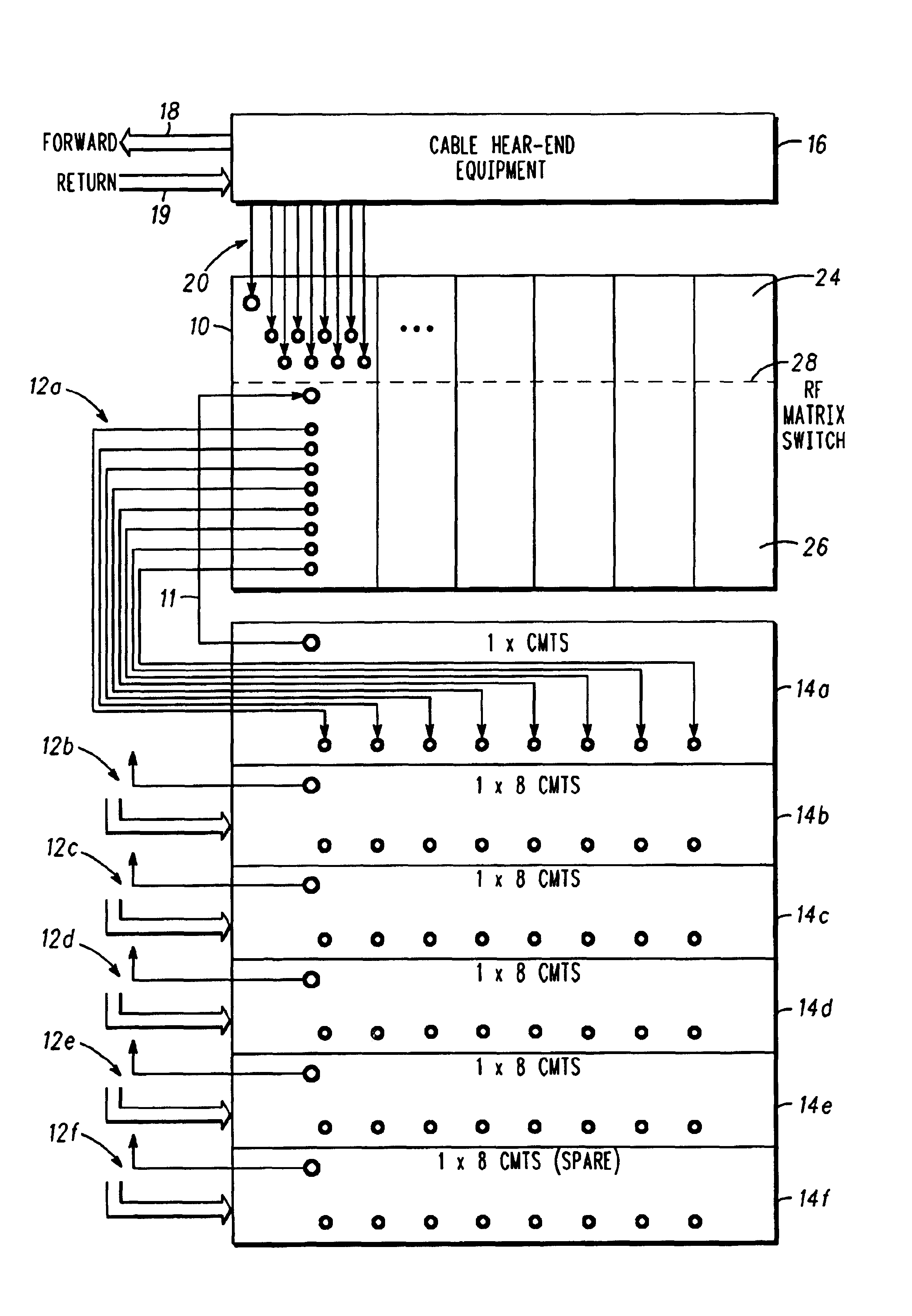
[0013]An RF Matrix Switch according to one embodiment of the present invention with a vertical height of about 5.25 inches (3U standard height) provides accessible connection points for five primary CMTSs and one backup CMTS. One (or optionally two) forward path cable(s) and eight return path cables are connected from each of six CMTSs to the RF Matrix Switch, corresponding to a total of six (or optionally twelve) forward path cables and forty-eight return path cables. Cables having a smaller diameter are used for return path connections. Quick-connect / disconnect termination of the cables allows installation and replacement of cables with minimum access.
[0022]The invention being angled and having separate connector boards for each surface area of the angled panel, insures that the coaxial connections between the Cable TV Network and the RF Matrix Switch connector panel, provide isolation for the Multi-layer Transmission line Mid-plane board (where all of the switching is performed). In designs where extremely low loss PC board material is required to produce low loss and reliable transmission lines, ceramic materials that are commonly used in microwave are required. This low loss ceramic material could be damaged by the shock of the constant insertion or disconnecting of RF Coaxial Connectors.

Problems solved by technology

Often, dozens or hundreds of cables must be connected to a network component wherein space for connection points is limited.
Connection points are therefore often crowded.
The access space constraints often cause installation and replacement of cables to be difficult and time consuming.
The additional number of connection points necessarily increases the size of network components to which cables are connected or increases crowding at the at the cable interface of the network components.
Increased crowding at connection points reduces access to connection points for cable installation and replacement.
A technician's impeded view of a connection point may cause the technician to disconnect an incorrect cable or to connect a replacement cable to an incorrect connection point.
Such errors are likely to decrease system availability.
Conventional cables having F-type connectors are overly crowded at such matrix switch connection points thereby impeding visual and physical service access to the connection points.
Standard F-Type connectors are mechanically secured to connection points by threaded collars, which require substantial access space for cable removal and installation.
Installation or replacement of CMTS units in a High Availability cable network having conventional connections at crowded interface panels is therefore disadvantageously time consuming and susceptible to incorrect connections.
The larger interface panels are disadvantageously wide or tall.
Cable service providers and other users of such interface panels disfavor using interface panels having wider or taller dimensions because such panels consume valuable cabinet space and often do not fit properly into existing cabinets or mounting structures.
For example, standard 6U interface panels having a vertical height of 10.5 inches do not meet customer marketing requirements for systems having superior space utilization.
The downward stresses often degrade an electrical connection at the joint between the cable and its terminating connector.

Method used


Image

  • Switch matrix packaging for high availability
  • Switch matrix packaging for high availability
  • Switch matrix packaging for high availability

Examples


Embodiment Construction

[0038]A cable network component interface according to an illustrative embodiment of the present invention is shown in FIG. 4. An RF Matrix Switch 10 is connectable by a first set of cables 12 to a set of Cable Modem Termination Systems (CMTS) 14A-14F and to a cable head-end network 16. The cable head end network communicates to the RF Matrix Switch 10 through a second set of coaxial cables 20.

[0039]The set of CMTS units 14A-14F include a plurality of primary CMTS units 14A-14E and a spare CMTS unit 14F. The illustrative embodiment of FIG. 4 includes five primary CMTS and one spare CMTS. It should be appreciated by persons skilled in the art that any number of primary CMTS units may be combined in a set with any number of CMTS units without departing from the spirit and scope of the present invention.

[0040]A forward path circuit 11 of each CMTS is connectable to a downwardly inclined panel 26 of the RF Matrix switch 10. An alternative embodiment of the present invention may include ...


PUM


Abstract

A cable interface system for a high availability, high frequency cable network. An example embodiment includes a Radio Frequency Matrix Switch which connects N cable head ends with N+1 Cable Modem Termination Systems by a set of coaxial cables having 75 ohm BNC connectors in the forward path and 75 ohm connectors in the return path. Push-on type connectors along with reduced size connectors and cables provide increased access to connection points on interface panels. Angled interface panels on the Radio Frequency Matrix Switch provide increased connector space. Grouping of connection points on a the Radio Frequency Matrix Switch simplifies installation and replacement of cables. The Radio Frequency Matrix Switch can immediately switch a spare Cable Modem Termination System into service as necessary to avoid down time.

Description

FIELD OF THE INVENTION[0001]The present invention relates generally to cable network interface connections and more specifically to a system for providing high availability for a cable network.BACKGROUND OF THE INVENTION[0002]Radio Frequency Matrix Switches (RF Matrix Switches) are going to be required in order to provide High Availability (HA) internet protocol (IP) telephony over a cable television network. The RF Matrix Switches are physically and logically placed between a set of DOCSIS (Data Over Cable Service Interface Specification) Cable Modem Termination Systems (CMTS) and cable TV head-end network equipment. The cable TV network head-end equipment is typically an RF network of combiners and splitters that eventually exit the cable TV network head-end as an optical signal via a laser in the forward path; or enter into the head-end as an optical signal via Optical receiver from the return path. In the United States as an example, the forward path signals range from 54 MHz to...

Claims


Application Information

Patent Timeline
IPC IPC(8): H04N7/10H04N7/173H04N21/61
CPCH04N7/104H04N21/6168H04N21/6118H04N7/17309
Inventor SIMOES, MICHAEL J.MORAN, III, JOHN L.IVAS, STANLEY
Owner ARRIS ENTERPRISES LLC
Learn More