System for operating one or more lasers to project a visible line onto a surface

a laser and surface technology, applied in the direction of instruments, movable markers, sport apparatus, etc., can solve the problem of substantial optical energy loss

Inactive Publication Date: 2005-05-24
THOUGHT DEVMENT
View PDF10 Cites 22 Cited by
  • Summary
  • Abstract
  • Description
  • Claims
  • Application Information

AI Technical Summary

Benefits of technology

[0018]It is expected that the power delivery requirements for each laser source can vary considerably for each installation, depending upon such variables as the range of expected ambient lighting conditions, the distance emitted optical energy must traverse before contacting the target surface, and the actual width dimension of the line to be displayed. For a line width of approximately 4 to 6 inches (10 to 15 cm), excellent results have been achieved from distances in excess of several hundred feet using 40 W, frequency doubled, Q-switched Nd:YAG lasers each adapted to generate laser pulses at a wavelength of 532 nm. Emission at this wavelength is especially preferred since it is very close to the peak (555 nm) of the eye's sensitivity. By comparison, in an argon laser operating in continuous wave (cw) mode, roughly half of the output is at 514 nm (58% as bright as the same beam at 555 nm), another 30% is at around 480 nm (18% as bright) and the remaining 20% is at around 440 nm (barely visible to he human eye). Thus, such an argon laser would have to deliver up to three or four times as much power to match the visibility of the Nd:YAG laser. Notwithstanding the relative difference in visibility, the inventors herein contemplate that one or more cw-mode lasers can be used in conjunction with one or more pulse mode lasers to provide a single, composite visible line, if desired. Moreover, and with particular regard to an illustrative embodiment that uses two laser sources to generate each visible line, it is also contemplated that the first laser source may be configured to deliver a beam which has a different power level than the second laser source, and that the respective power levels may be altered as necessary to compensate for changes in ambient lighting conditions.

Problems solved by technology

Substantial optical energy is lost when the optical output of several lasers are coupled together in this fashion.

Method used


Image

  • System for operating one or more lasers to project a visible line onto a surface
  • System for operating one or more lasers to project a visible line onto a surface
  • System for operating one or more lasers to project a visible line onto a surface

Examples


Embodiment Construction

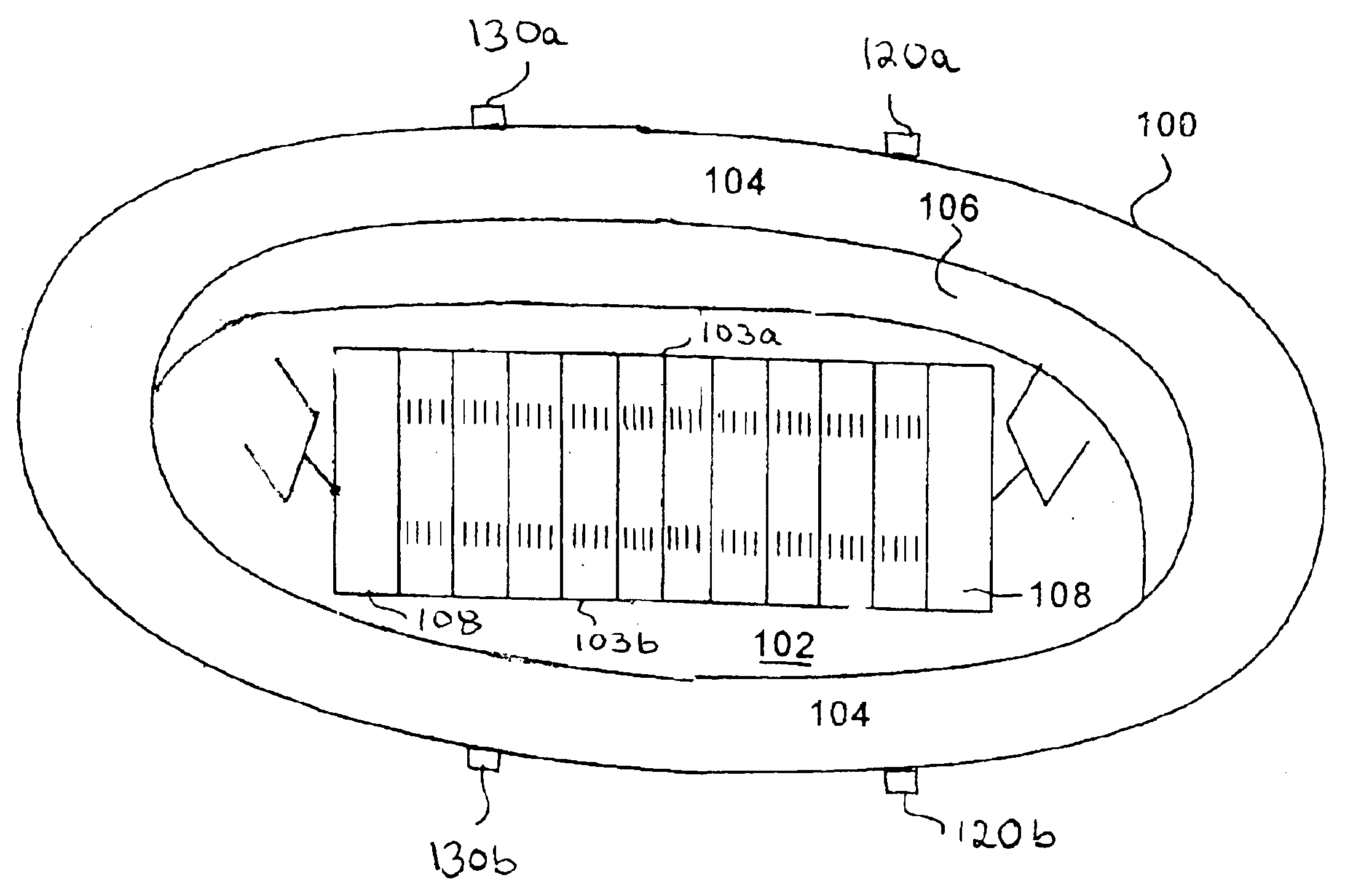
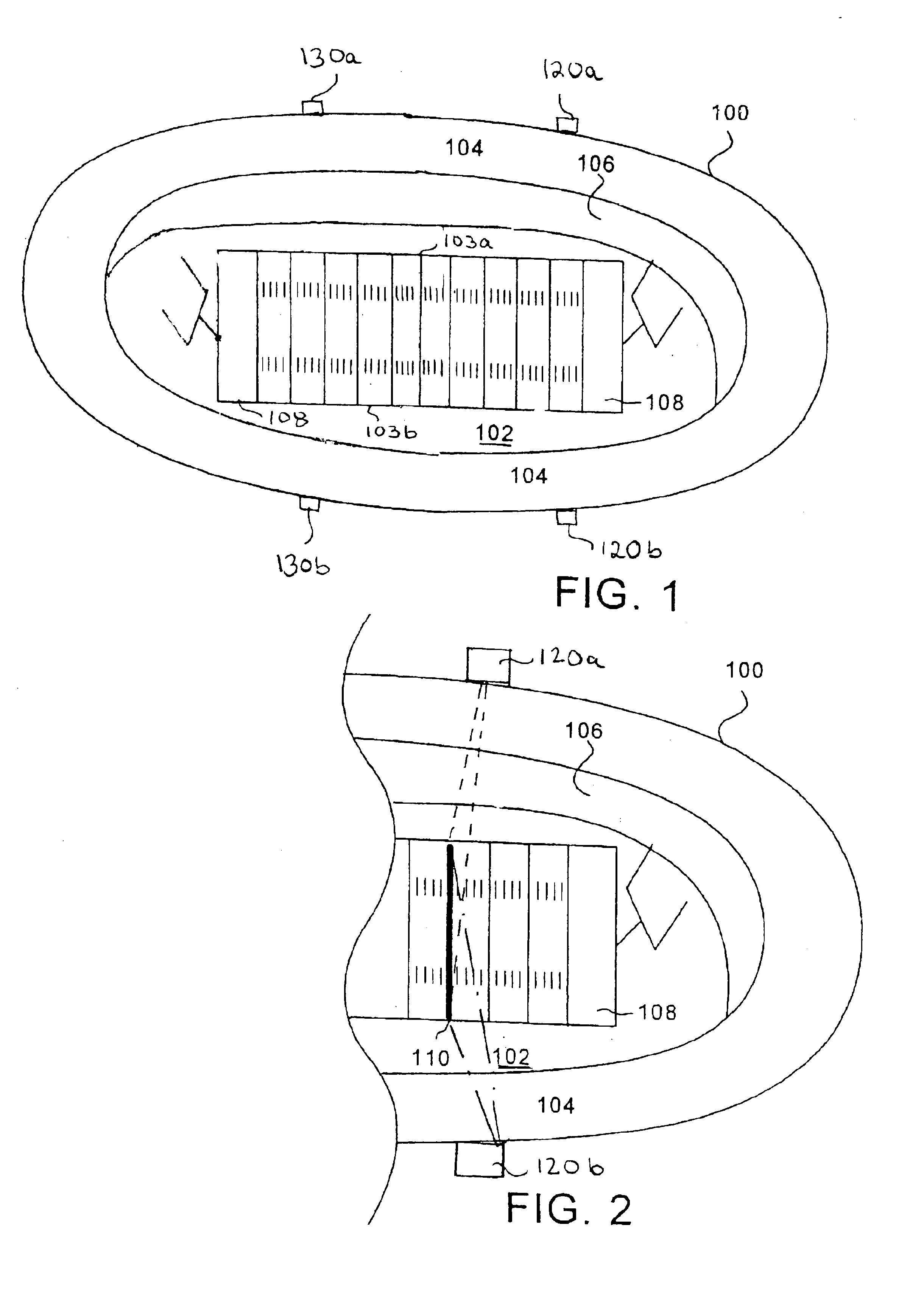
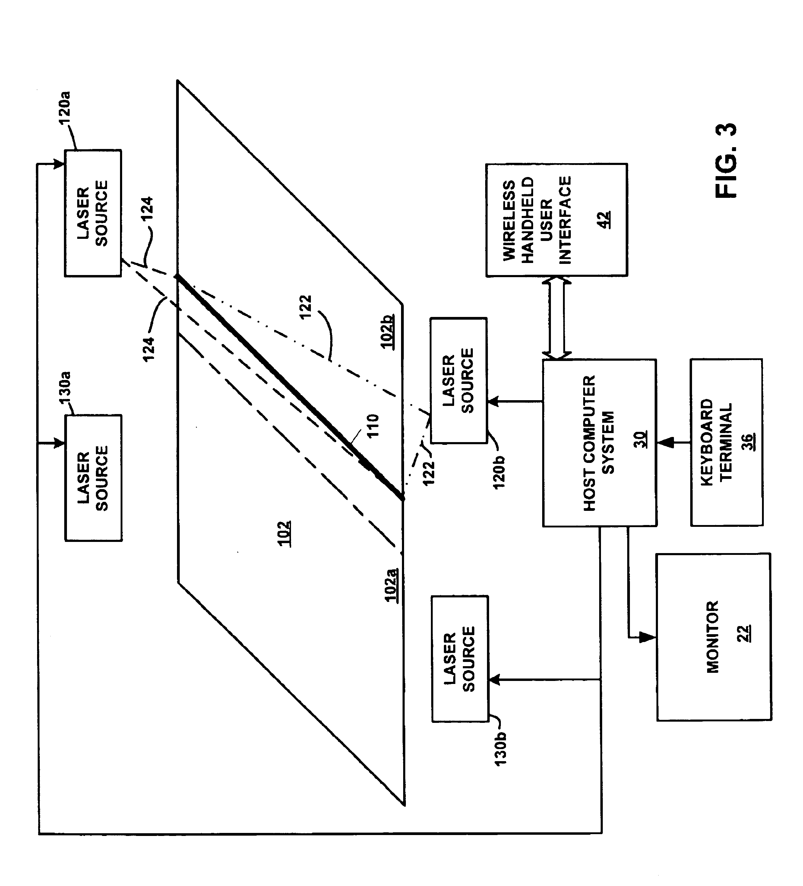
[0030]In connection with the exemplary football stadium installation depicted in FIGS. 1 and 2, it will be understood that the term “target surface” refers to the surface of an athletic field that is entirely or substantially covered by real or artificial turf grass. By appropriate beam wavelength, output power level selection, and / or placement of multiple laser sources, the poor light scattering performance of such non-smooth surfaces can be overcome so that spectators can easily see the line(s) so-projected—from most, if not all, vantage points within the seating area of a stadium or arena—even in peak daylight ambient lighting conditions. It should thus be understood that although the exemplary embodiments illustrated and described herein relate specifically to the projection of a visible straight line onto the grass surface of a football field, the teachings of the present invention are equally applicable to the projection of other types of lines—including images, logos, adverti...


PUM


Abstract

At least one temporary visible reference line is projected onto a target surface, as for example, an athletic field, by several laser sources. A first laser source emits optical energy—at a wavelength of between 380 nm and 750 nm—along at least a first selectable path upon the target surface so as to form a temporary line thereon. A second laser source disposed at a second elevated, stationary location relative to the target surface different from the first stationary location emits optical energy along at least a second selectable path upon the target surface so as to form a temporary line thereon. In some instances, each laser light source may be capable of traversing the entire width of the target surface, in which case each laser source covers a discrete region. In other cases, respective laser sources arranged on opposite laterals sides of the target surface can be included so that segments contiguous with those projected by a corresponding one of the first and second laser sources can be generated to form a temporary line that does traverse the entire width of the target surface.

Description

REFERENCE TO RELATED APPLICATIONS[0001]This application is a continuation-in-part of U.S. patent application Ser. No. 10 / 385,219 filed on Mar. 10, 2003, now U.S. Pat. No. 6,796,041 and entitled “SYSTEM FOR OPERATING ONE OR MORE SYNCHRONIZED LASERS TO PROJECT A VISIBLE LINE ONTO A SURFACE” and of U.S. patent application Ser. No. 10 / 385,218 filed on Mar. 10, 2003, now U.S. Pat. No. 6,751,880 and entitled “SYSTEM AND METHOD FOR OPERATING GROUPS OF LASERS TO PROJECT A VISIBLE LINE OF DEMARCATION ONTO DISCRETE REGIONS OF AN ATHLETIC FIELD”, both of which are continuations-in-part of co-pending U.S. patent application Ser. No. 10 / 320,304 filed on Dec. 16, 2002 and entitled “SYSTEM AND METHOD FOR DYNAMICALLY MARKING ATHLETIC FIELDS USING A HANDHELD USER INTERFACE”.BACKGROUND OF THE INVENTION[0002]1. Field of the Invention[0003]This invention relates generally to the projection of visible lines onto surfaces upon which persons are standing (e.g., athletic fields during sporting or entertain...

Claims


Application Information

Patent Timeline
Patent Type & Authority Patents(United States)
IPC IPC(8): G01C15/00
CPCG01C15/004
Inventor DINICOLA, BRIAN K.
Owner THOUGHT DEVMENT
Why Eureka
Try Eureka