Constant density printer system

a printer system and constant density technology, applied in the field of impact printers, can solve the problems of hammer tips striking against inked ribbons, affecting the effect of print quality, and complicated arrangement, so as to improve print quality, reduce the “apparent viscosity", and reduce the effect of viscosity

Inactive Publication Date: 2005-05-24
PRINTRONIX INCORPORATED
View PDF29 Cites 7 Cited by
  • Summary
  • Abstract
  • Description
  • Claims
  • Application Information

AI Technical Summary

Benefits of technology

[0026]Furthermore, the use of a multi-viscosity ink provides additional improvements to print quality. The lower viscosity inks in the ink mixture helps lower the “apparent viscosity” at lower operating temperatures, while the higher viscosity inks help maintain sufficient viscosity for printing applications at the higher end of operating temperatures. The net effect is that the “apparent viscosity” remains more nearly constant across the printer's operating temperature range than with single or mono-viscosity inks. Using multi-viscosity ink mixtures helps reduce or eliminate the propensity for ink smearing on the print media and ink migration into the print...

Problems solved by technology

This causes their hammer tips to strike against an inked ribbon as it traverses between the hammers and the print media.
In dual-row hammer line matrix printers as opposed to single row hammer line matrix printers, the arrangement is slightly more complicated.
This has adverse print quality effects.
The defects in print quality when ink is depleted from a ribbon whether it be a dual-row hammerbank or a single-row hammerbank can become quite apparent.
When the ink supply in the ribbon gradually decreases, it causes undesirable effects.
Firstly, the density, or darkness of the printed dots decreases continuously as ink is consumed.
Secondly, pre-inked ribbon becomes damaged as ink is consumed.
This is because the ink, which lubricates the ribbon fibers, is depleted.
Damaged ribbon can result in print failure at the edges of the media, as well as certain kinds of mechanic...

Method used


Image

  • Constant density printer system
  • Constant density printer system
  • Constant density printer system

Examples


Embodiment Construction

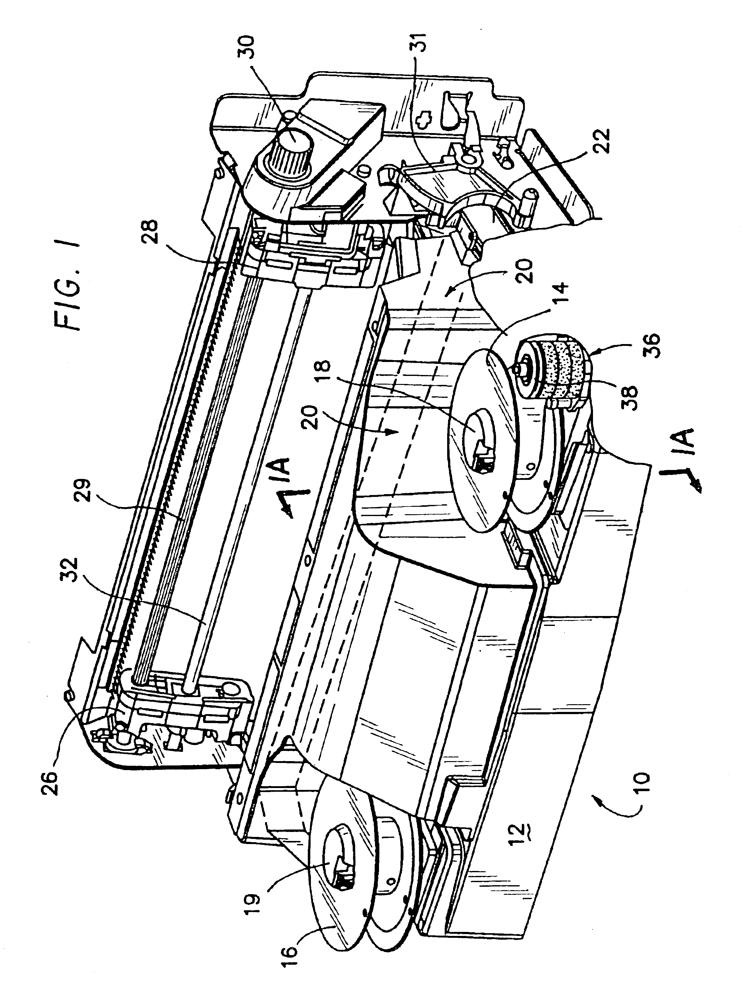
[0067]FIG. 1 shows a perspective view of this invention in the form of an impact line printer 10. The impact line printer 10 can be mounted on a stand, a base, or can be free standing in a cabinet. In this particular case, the line printer 10 has been shown in a configuration with respect to the operating elements and none of the appurtenant support material or devices.

[0068]The line printer 10 has a base 12 which mounts a pair of ink ribbon spools 14 and 16. The ribbon spools 14 and 16 are emplaced upon hubs or spindles 18 and 19. The hubs 18 and 19 have spring loaded catches which tend to secure the ribbon spools onto them for driving purposes.

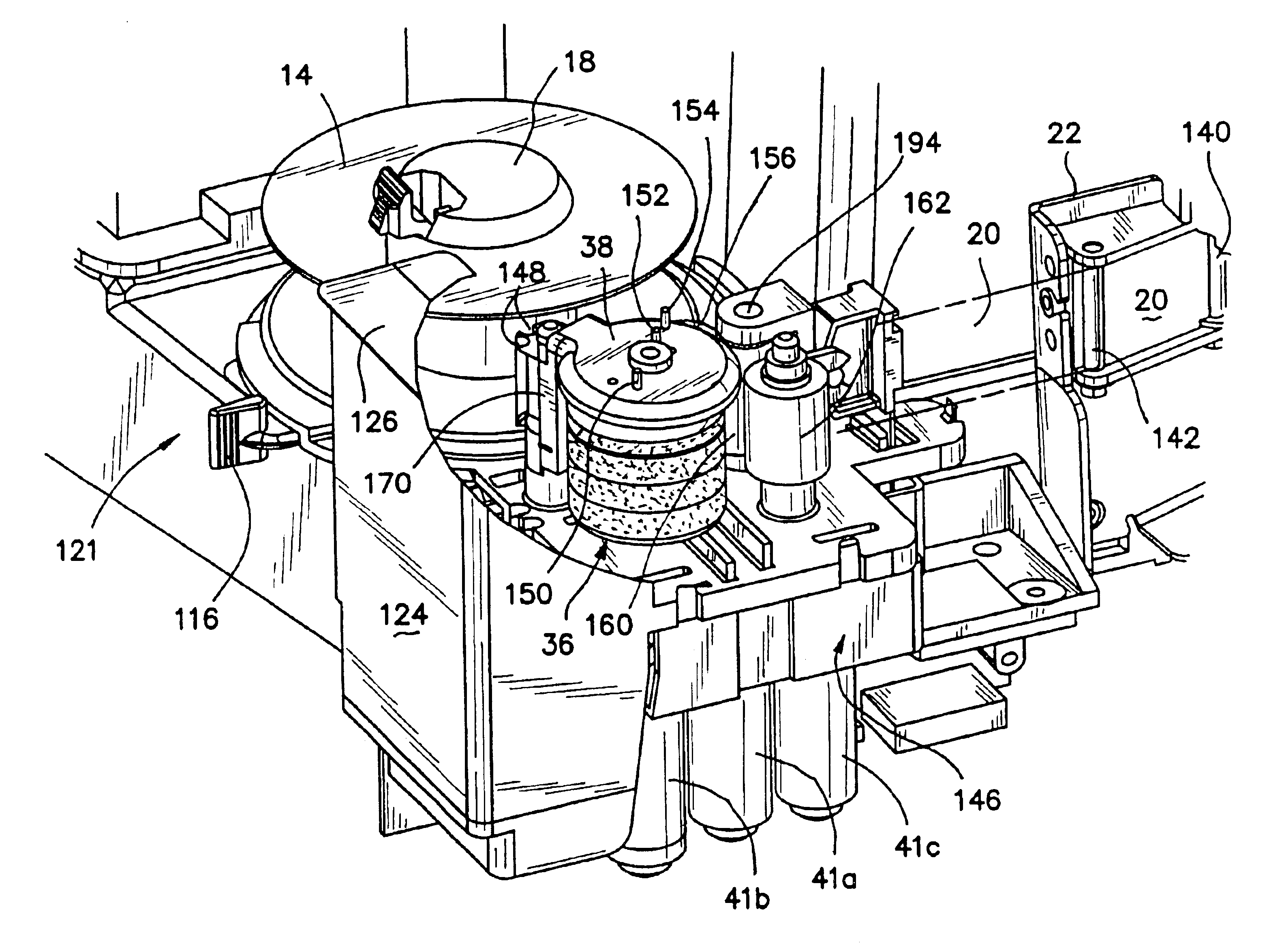
[0069]The ribbon spools 14 and 16 provide for the traversal of a ribbon 20 which is shown in dotted configuration. The ribbon 20 traverses at a slight angle in order to accommodate the ribbon passing and being struck at various portions as it traverses over the hammerbank in the manner set forth hereinafter.

[0070]The ribbon 20 shown in the d...


PUM


Abstract

An ink density closed loop control system for an ink ribbon of an impact printer having a reservoir roller formed of an ink absorbent material with at least one or more channels within the reservoir roller fluidly connected to a pump and ink supply. A transfer roller can contact the reservoir roller for imparting ink to the ink ribbon. A sensor senses the relative amount of ink on the print ribbon and an electrical drive responsive to the sensor drives the pump for a flow of ink to the one or more channels. The sensor can sense ink on different segments of the ribbon and, with two or more channels in the reservoir roller can distribute ink to two or more segments of the reservoir roller depending upon the ink sensed at a particular segment of the ribbon. A further enhancement of this invention provides a multi-viscosity ink to compensate for changes in ambient temperature conditions.

Description

REFERENCE TO RELATED APPLICATIONS[0001]This is a continuation-in-part application of U.S. patent application Ser. No. 10 / 387,917, entitled “Constant Density Printer System”, filed Mar. 12, 2003, now U.S. Pat. No. 6,695,495, patented on Feb. 24, 2004.BACKGROUND[0002]1. Field of the Invention[0003]This invention relates to impact printers, and more specifically, to maintaining the ink content on the print ribbon of such printers.[0004]2. Related Art[0005]The prior art of impact printing in line matrix printers is accomplished when hammers are released from retention. This causes their hammer tips to strike against an inked ribbon as it traverses between the hammers and the print media. The print media is backed-up on the other side by a hard platen, so that the impact from the hammer tip leaves ink dots on the print media. The print media can be paper, labels, multi-layer forms, including plastic and combinations of plastic and paper.[0006]The inked print ribbon traverses at an angle ...

Claims


Application Information

Patent Timeline
IPC IPC(8): B41J2/22
CPCB41J2/22
Inventor WHITE, DENNIS R.JOU, JENG-DUNGBARRUS, GORDON B.CHANG, Y. GRANTGEMMELL, JOHN W.KINLEY, JOHN S.CHIU, LIHUMOORE, KEVIN P.
Owner PRINTRONIX INCORPORATED
Why Eureka
Try Eureka