Method and system for high speed tray unloading and mail transporting

Inactive Publication Date: 2005-05-24
BOWE BELL HOWELL
View PDF26 Cites 29 Cited by
  • Summary
  • Abstract
  • Description
  • Claims
  • Application Information

AI Technical Summary

Benefits of technology

[0019]The tray unloading apparatus comprises a tray control module and a tray removing module. A full tray incoming transport delivers mail trays to the tray control module. The tray control module then inverts the tray. A tray guide prevents the tray from falling out of the tray control module while the tray is being inverted. Once the tray is inverted, the tray removing module lifts the inverted tray away, leaving the contents on the tray control module. The tray control module then delivers the contents to the c

Problems solved by technology

While there are numerous prior art apparatus for 
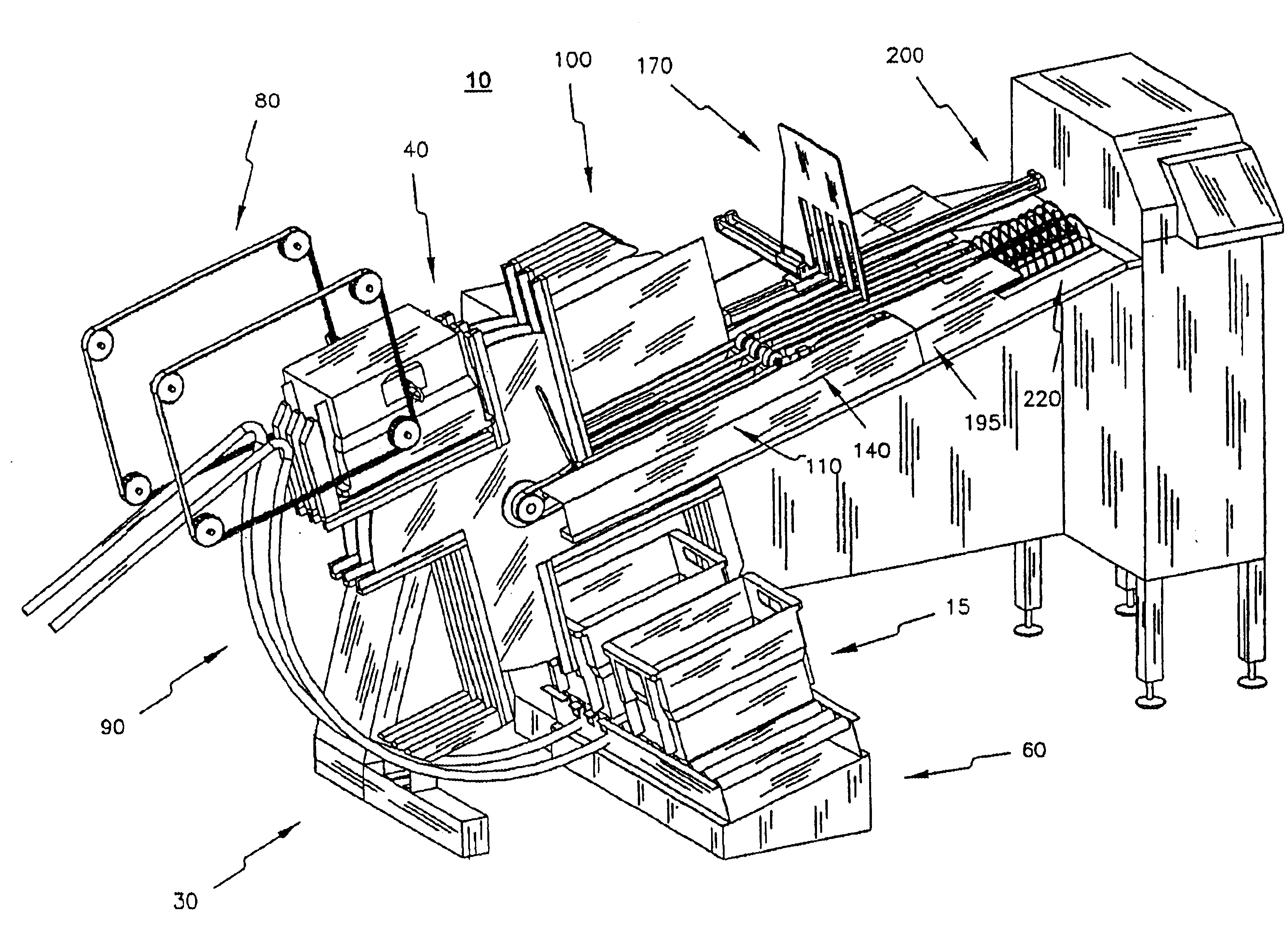
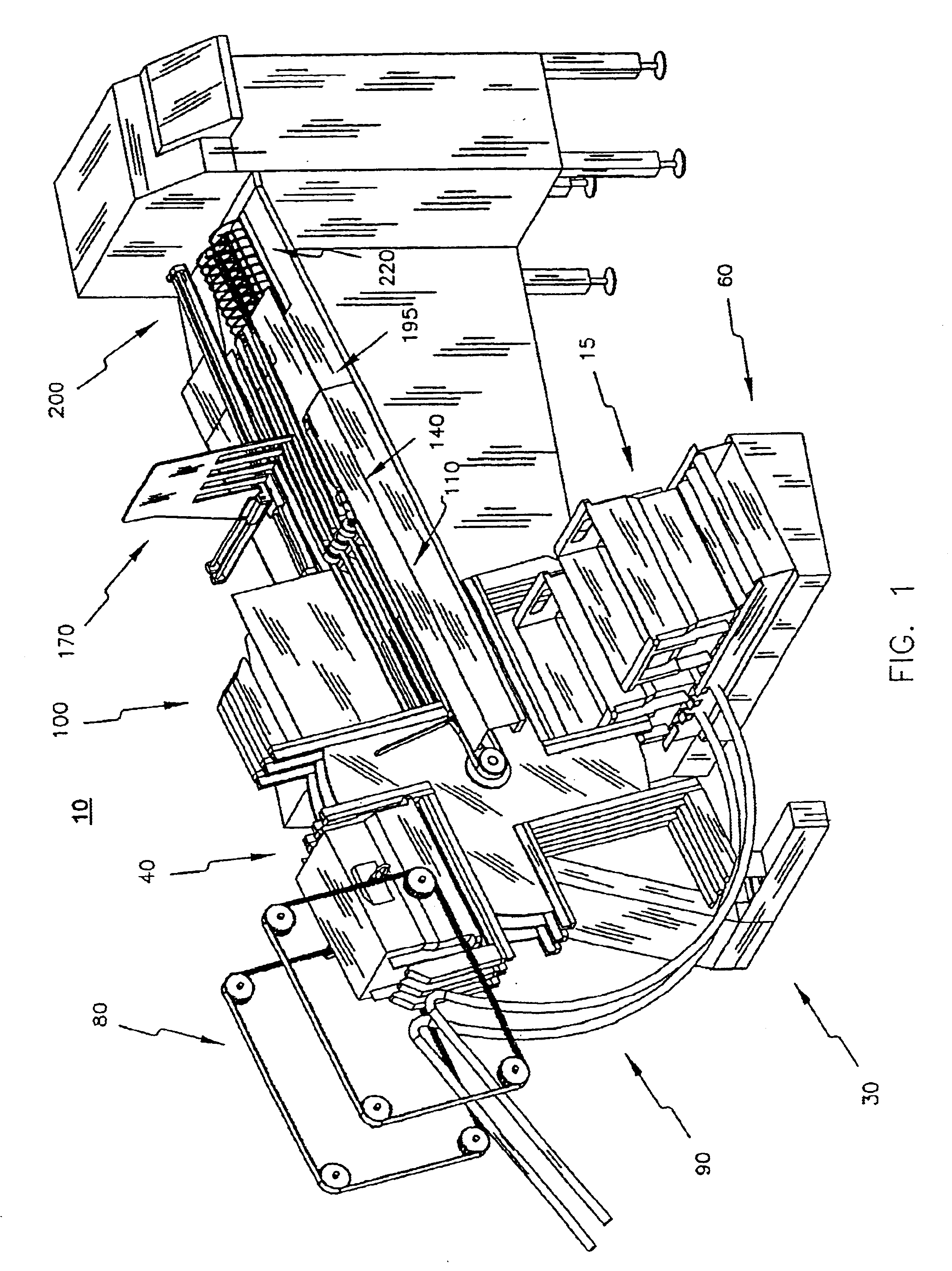
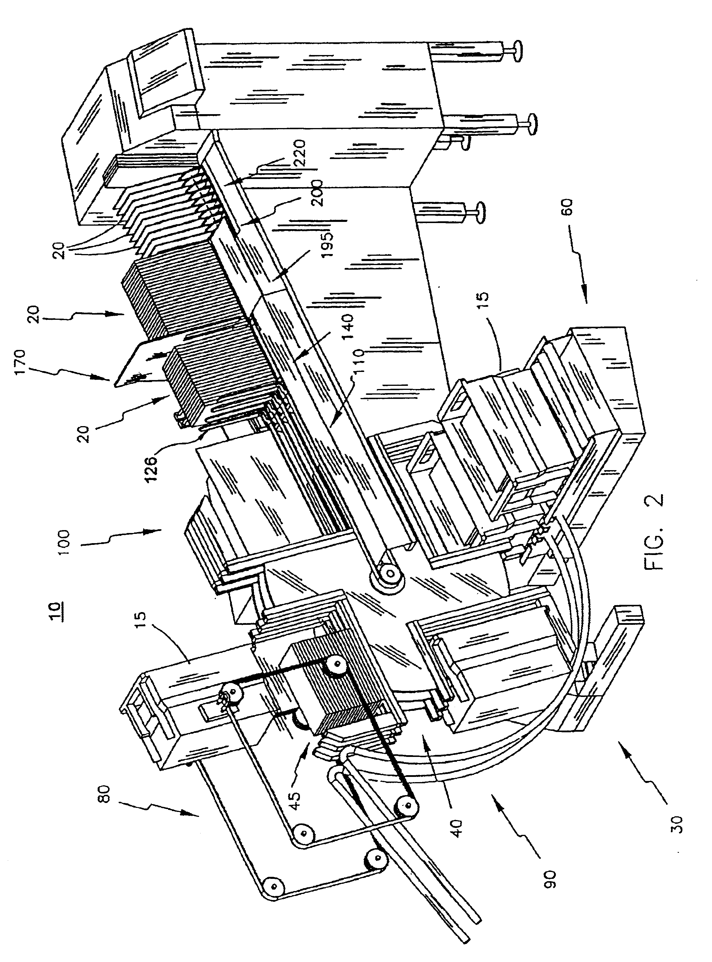
processing mail, there are no known apparatus to receive a series of mail trays containing mail, continuously unload these trays in proper orientation, and then controllably deliver the mail to a desired mail processing machine in a fast and efficient manner.
However, such devices are relatively complicated, having numerous movable components to manipulate the tray, and is relatively time consuming.
Further, the tray removal requires numerous movable parts, including pneumatic cylinders.
Such multiple movements and parts can result in a relatively lengthy and non-continuous operation, and overall slower processing times. Further, the apparatus could be subject to lengthy down times if any of these components fatigue or fail.
Due to the numerous components, this apparatus is relatively expensive to manufacture and maintain.
Further, it appears that this device also remains largely manual in operation.
Such known devices in general are inappropriate for mail processing applications, where the contents must be precisely handled and positioned.
Such known prior art devices cannot adequately achieve the same.
The machine includes a relatively complicated system of belts and rollers in association with a wheel for inverting the crates.
However, this machine in not suitable for mail processing.
The machine does not precisely control and position

Method used


Image

  • Method and system for high speed tray unloading and mail transporting
  • Method and system for high speed tray unloading and mail transporting
  • Method and system for high speed tray unloading and mail transporting

Examples


Embodiment Construction

[0088]While the invention is susceptible of embodiment in many different forms, there is shown in the drawings and will be described herein in detail a preferred embodiment of the invention. It should be understood however that the present disclosure is to be considered an exemplification of the principles of the invention and is not intended to limit the spirit and scope of the invention and / or claims of the embodiment illustrated.

[0089]FIG. 1 illustrates the present invention 10 which is comprised of three main components, a tray unloading apparatus 30, a conveyor assembly 100, and a spiral transport system 200. The tray unloading apparatus 30 sequentially and continually unloads trays of mail, and controllably delivers the unloaded mail to the conveyor assembly 100. The conveyor assembly 100 transports the unloaded mail away from the tray unloading apparatus 30 and delivers the mail to the spiral transport system 200. The spiral transport system 200 receives and spaces small grou...


PUM


Abstract

A method and apparatus for high speed tray unloading and mail transporting includes a tray unloading apparatus which receives a continuous stream of mail trays and sequentially unloads them in proper orientation onto a conveyor assembly; a dual conveyor system for delivering the unloaded mail to a transport system; and a spiral transport system having optimal drive means for controllably moving mail pieces from one location to another.

Description

[0001]This application is a divisional of application Ser. No. 09 / 829,725 filed Apr. 10, 2001, now U.S. Pat. No. 6,722,838.[0002]The present invention relates to a method and system for high speed tray unloading and mail transporting. In particular, the method and system of the present invention comprises three novel components. First is a tray unloading apparatus which sequentially receives mail trays containing any number of mail pieces, and continuously unloads the mail onto a conveyor system in proper orientation. Second is a dual conveyor belt system which collects the mail and delivers the mail to a transport system. Third is a transport system comprising a spiral having optimal drive means for controllably moving small groups of mail from one location to another, for example from one mail processing apparatus component to another.BACKGROUND OF THE INVENTION[0003]Many businesses and postal services utilize high speed mail processing machines to rapidly process and / or transport...

Claims


Application Information

Patent Timeline
IPC IPC(8): B65H1/14B65H1/26B65H1/30
CPCB65H1/025B65H1/26B65H1/30B65H2701/1916B65H2301/321B65H2301/422542
Inventor SVYATSKY, EDUARDVLADIMIROVICH, PASHKEEV NIKOLAIMARKOVICH, SHEIHON BORISMICHAILOVICH, SVYATSKY ADOLFBELYAEV, VADIM
Owner BOWE BELL HOWELL
Why Eureka
Try Eureka