Miniaturized temperature-zone flow reactor

a flow reactor and temperature-zone technology, applied in the field of miniaturized temperature-zone flow reactors, can solve the problems of limited temperature change rate, insufficient effectiveness of sample chambers known up to now, and low efficiency of methods

Inactive Publication Date: 2005-05-24
INSTITUT FUER PHYSIKALISCHE HOCHTECH
View PDF10 Cites 97 Cited by
  • Summary
  • Abstract
  • Description
  • Claims
  • Application Information

AI Technical Summary

Benefits of technology

[0006]It is an object of the present invention to provide a miniaturized temperature-zone flow reactor that permits the performance of thermally controlled biochemical and molecular-biological processes, respectively, in particular, the method of polymerase chain reaction, more effectively than the prior art.

Problems solved by technology

In this respect, the effectiveness of the sample chambers known up to now is considered as not being sufficient.
In spite of the advantages obtained by this device, it involves substantially the disadvantage that also this sample chamber has to be heated and cooled as a whole which only permits limited rates of temperature changes.
Particularly, when further reducing the size of the sample, the parasitic heat capacity of the sample chamber and that of a necessary temper block, if any, becomes more weighty compared to the sample fluid, so that the possible high temperature cycle rates which are attainable, in principle, with small liquid volumes cannot be obtained, whereby the effectiveness of the method is comparatively low.
Moreover, a comparatively expensive control system is necessary each time a constant temperature schedule for a same fluid is to be obtained, and the heating and cooling power provided are substantially consumed in the components surrounding the sample fluid rather than in the sample fluid itself.
The manipulation of such a device, however, is rather impracticable and requires a high production skill in the manufacture of such devices, so that they are completely unsuited for serial production.
This solution, however, is disadvantageous because, on the one hand, there is required a very precise, structured procedure for manufacturing the membranes provided therein, and, on the other hand, due to the set-up of the device described there, the retention time of the sample fluid in the cooling zone ranges is undesiredly high, at least at partial passages, which can lead to the formation of undesired by-products when carrying out PCR.

Method used


Image

  • Miniaturized temperature-zone flow reactor
  • Miniaturized temperature-zone flow reactor
  • Miniaturized temperature-zone flow reactor

Examples


Embodiment Construction

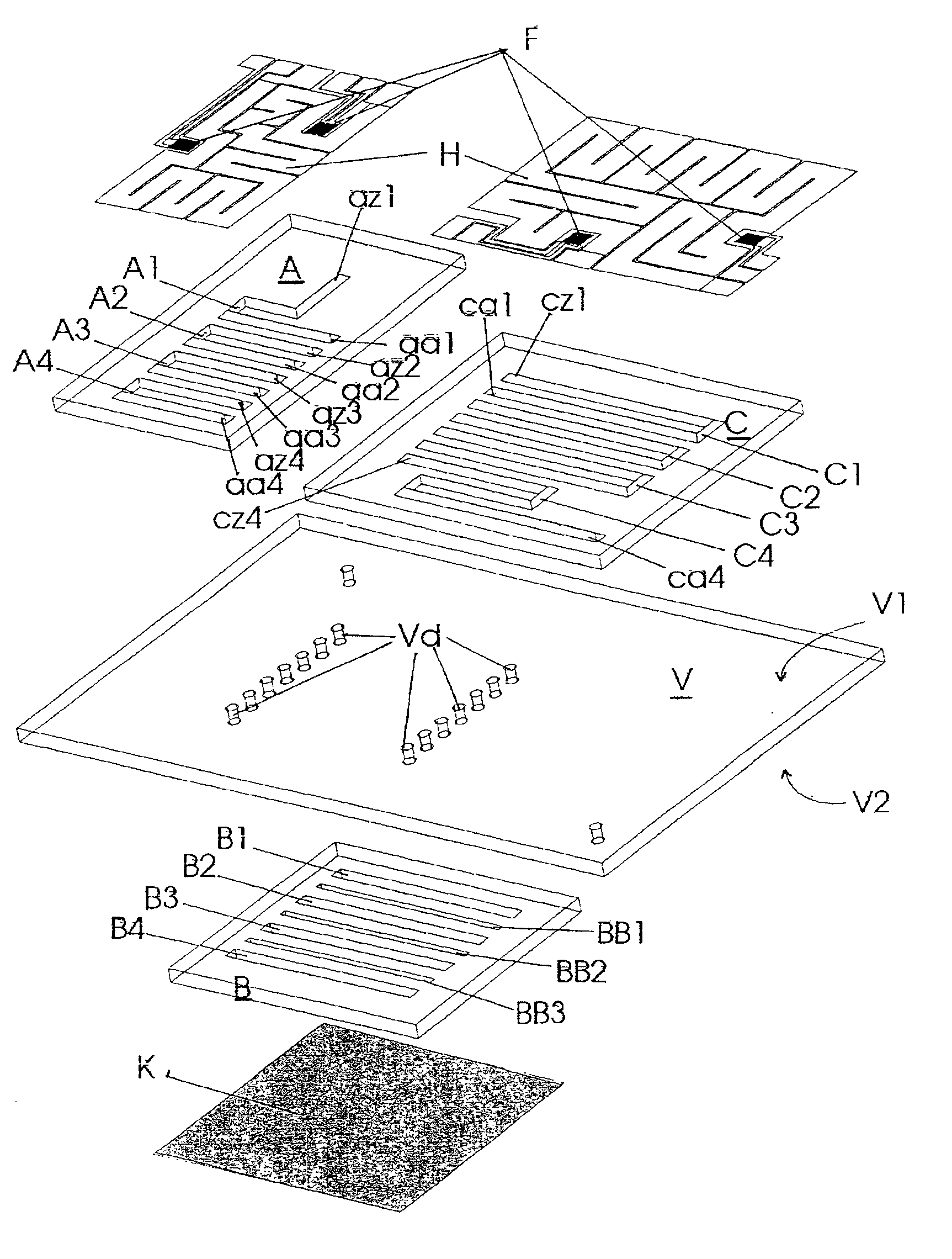
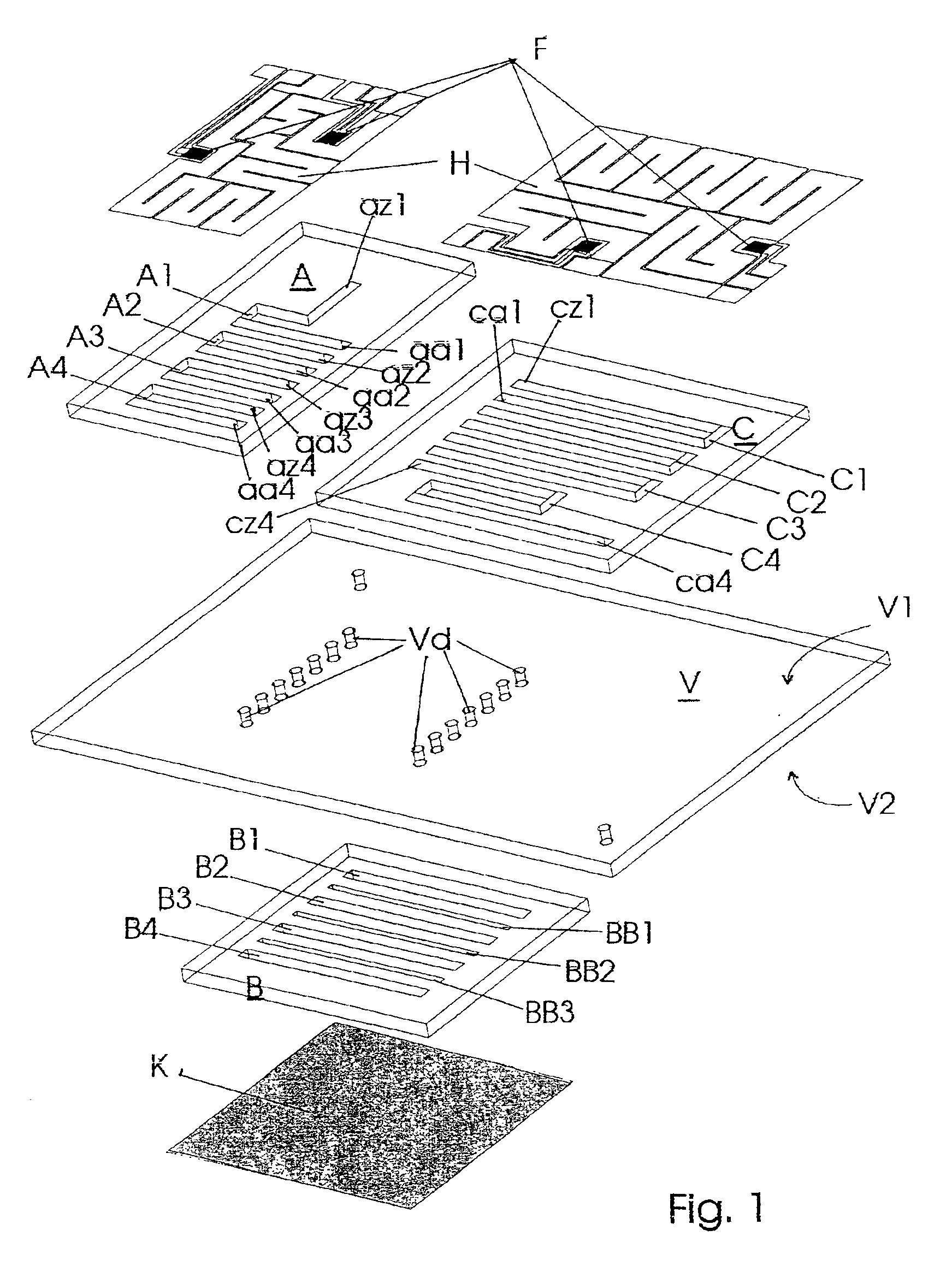
[0018]In FIG. 1 a miniaturized temperature-zone flow reactor is shown in an exploded view. For the sake of simplicity, only one closed flow path is shown in the example, the course of which will be described in the following. To begin with, there is provided a first substrate chip A which, in the example, has the external dimensions (length, width, thickness) of (8×13×0.5) mm and into one side of which channels are inserted that will have a length of 9 mm, a width of 0.536 mm and a depth of 0.380 mm. In the present example, the entire single channel section is to be understood by the here designated length. Said channel section lies, for example, between an inlet opening az2 and an associated outlet opening aa2, so that this channel section holds a volume of 0.9 μl in the present example. Furthermore, a third substrate chip C is provided which, in the example, has the external dimensions (length, width, thickness) of (14×13×0.5) mm and into one side of which channels are inserted th...


PUM

PropertyMeasurementUnit
sizeaaaaaaaaaa
depthaaaaaaaaaa
widthaaaaaaaaaa

Abstract

A miniaturized temperature-zone flow reactor, used for thermally controlled biochemical or molecular-biological processes, especially polymerase chain reaction (PCR) enables more efficient reactions by providing at least one closed flow path which is divided into three partial paths (A1 . . . An; B1 . . . Bn and BB1 . . . BBn−1; C1 . . . Cn) with the reactor having three substrate chips (A; B; C) which are made of a material having a high heat conductivity, and which have defined channel sections that are spaced apart relative to each other, and are connected by a connecting chip (V) made of a poor heat-conductive material. The substrate chips (A; B; C) are maintained at different temperatures by various means, including the use of controlling heating elements in contact with the chips.

Description

BACKGROUND OF THE INVENTION[0001]The invention relates to a miniaturized temperature-zone flow reactor used for thermally controlled biochemical and molecular-biological respectively, in particular for the method of the so-called polymerase chain reaction, referred to as PCR in the following, in which definite sequences out of a mixture of DNA-sequences are amplified.[0002]When carrying out thermally controlled biochemical and molecular-biologic processes, respectively, very often different temperatures are required to be applied to the processing steps. Such an applying of changing temperatures are of particular importance with the so-called PCR.[0003]The method of PCR has been developed in the recent years for amplifying definite DNA-sequences, and its principles have been specified by Darnell, J.; Lodish, H.; Baltimore, D. in “Molekular Zellbiologie, Walter de Gruyter, Berlin-New York 1994, p. 256 / 257”. It is an essential, inter alia, with said method that mixtures of DNA-sequenc...

Claims


Application Information

Patent Timeline
Patent Type & Authority Patents(United States)
IPC IPC(8): B01L3/00B01L7/00B01J19/00C12Q1/68
CPCB01J19/0093B01L3/5027B01L7/525B01L3/502707B01L3/502784B01L2300/1883B01L2300/0874B01L2300/0883B01L2300/1822B01L2300/1827B01L2300/0816
Inventor KOHLER, JOHANN MICHAELMOKANSKY, ANDREASPOSER, SIEGFRIEDSCHULZ, TORSTEN
Owner INSTITUT FUER PHYSIKALISCHE HOCHTECH
Why Eureka
Try Eureka