
Ultraviolet pasteurizer

a technology of ultraviolet light and pasteurizer, which is applied in the field can solve the problems of inability to sterilize microorganisms attached to walls, ceilings, floor surfaces, etc., and achieve the effect of reducing the size of ultraviolet light pasteurizer

Inactive Publication Date: 2005-05-24
KK TOPCON
View PDF13 Cites 28 Cited by
  • Summary
  • Abstract
  • Description
  • Claims
  • Application Information

AI Technical Summary

Benefits of technology

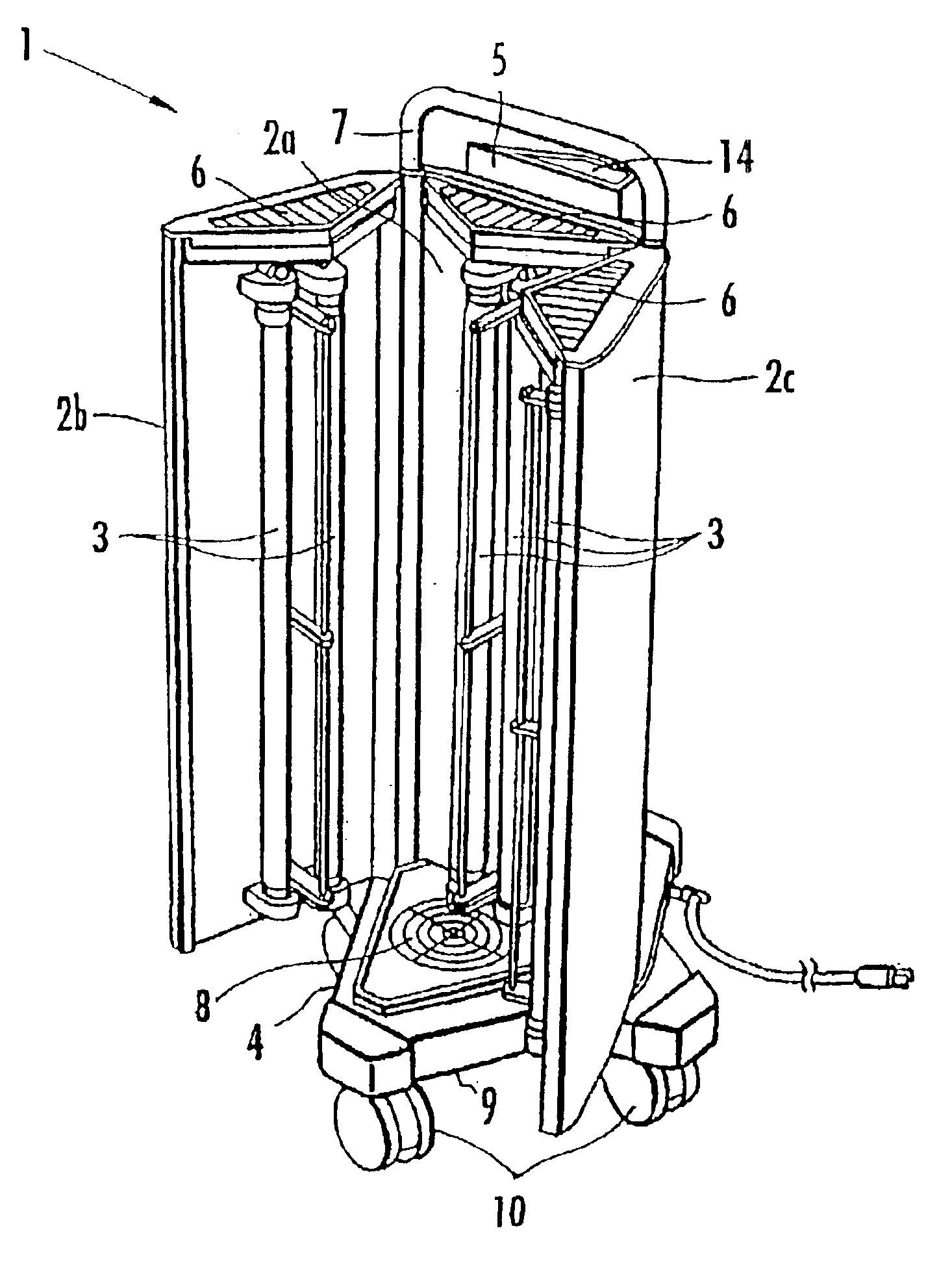
[0008]If a room free of a person is to be sterilized by the ultraviolet pasteurizer, then the light shield door is opened and the ultraviolet lamp is energized to emit ultraviolet radiation. Since the ultraviolet radiation is radiated out of the ultraviolet pasteurizer, the ultraviolet pasteurizer can sterilize microorganisms attached to surrounding wall, ceiling, and floor surfaces and also microorganisms suspended in surrounding air.
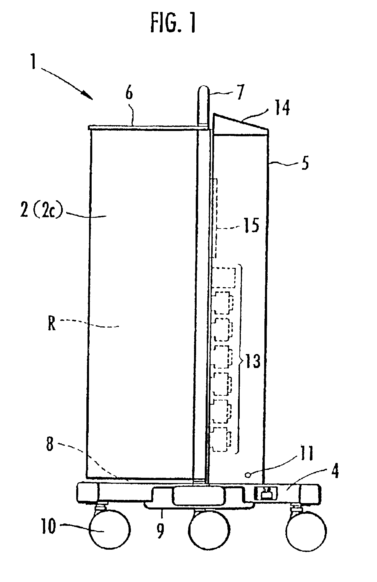
[0009]If a room occupied by a person is to be sterilized by the ultraviolet pasteurizer, then the light shield doors are closed. The fan introduces external air from the air inlet into the inner radiation chamber, and flows near the ultraviolet lamp. The introduced air is thus sterilized by ultraviolet radiation emitted from the ultraviolet lamp. The sterilized air is then discharged from the air outlet. Microorganisms suspended in the air in the room can therefore be sterilized. Since the ultraviolet radiation emitted from the ultraviolet lamp is blocked by the light shield door and hence does not leak out of the ultraviolet pasteurizer, the ultraviolet pasteurizer can safely sterilize the occupied room.
[0010]Furthermore, when the light shield door is opened, since the light shield door is angularly moved to direct the ultraviolet lamp outwardly, the ultraviolet lamp is exposed outwardly and hence the ultraviolet radiation emitted therefrom is not blocked, consequently, the ultraviolet pasteurizer can sterilize a wide area uniformly.
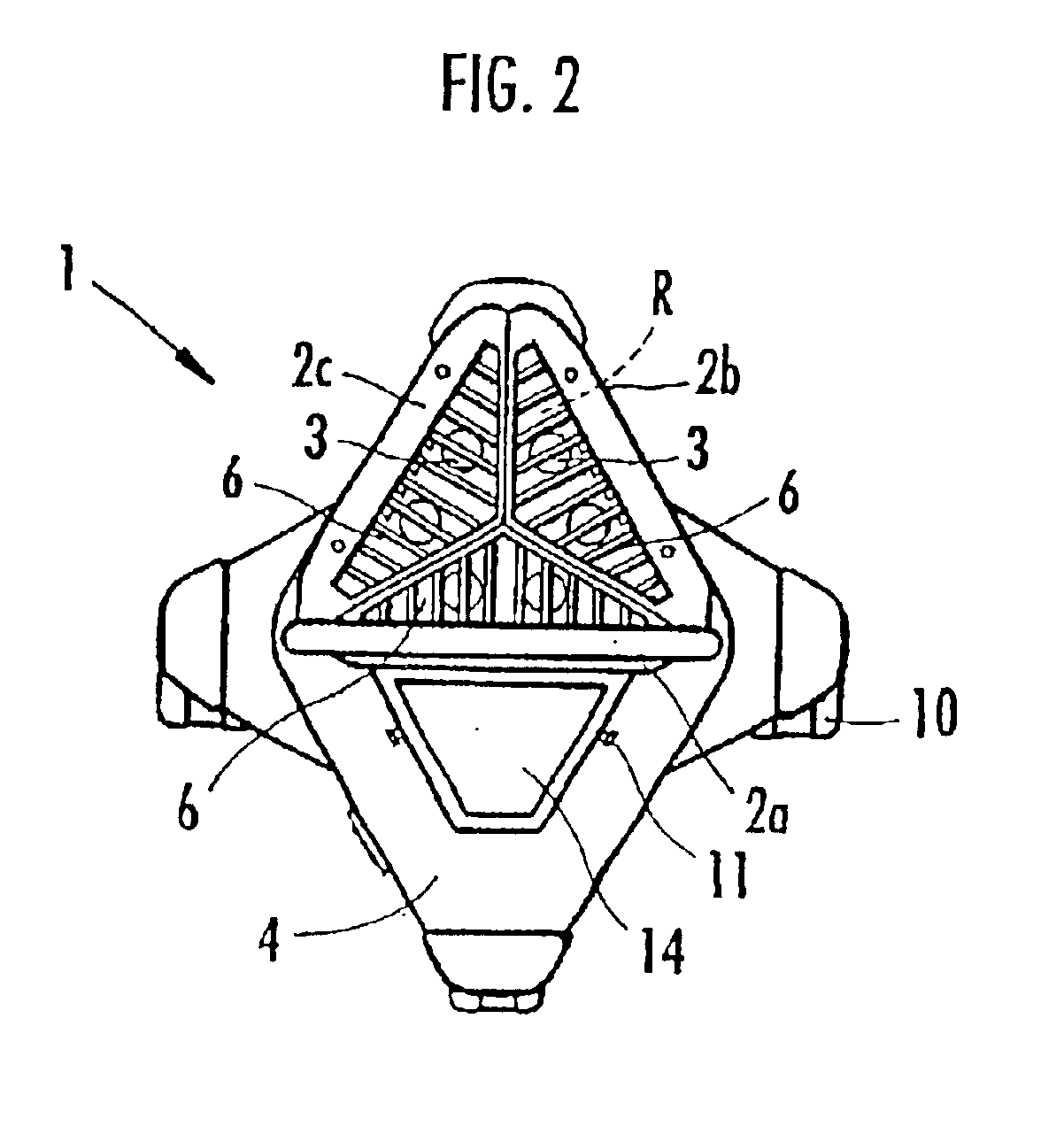
[0012]The side edges of the light shield doors are angularly movably coupled to each other. For opening the light shield doors, the side edges of the coupled light shield doors are brought into abutment against each other with the ultraviolet lamps facing outwardly. Since the ultraviolet lamps can radiate ultraviolet radiation in an angular range of 3600 in the circumferential direction, the ultraviolet pasteurizer can sterilize a wide area uniformly.
[0015]Moreover, according to the ultraviolet pasteurizer of the second aspect of the present invention, the ultraviolet pasteurizer may preferably further comprise a power supply unit for supplying electric energy to the ultraviolet lamps and the fan, the power supply unit being disposed in a space surrounded by the light shield doors which are opened with the side edges held in abutment against each other so that the ultraviolet lamps face outwardly. When the light shield doors are opened to orient the ultraviolet lamps outwardly, a space is created by surfaces of the light shield doors which are free of the ultraviolet lamps. Since the power supply unit includes a transformer and other components, a space of certain size is required to accommodate the power supply unit therein. The power supply unit can be housed in the space thus created by the light shield doors. With the power supply unit housed in the space, the space can effectively be utilized, and hence the ultraviolet pasteurizer can be reduced in size.

Problems solved by technology

The former type of ultraviolet pasteurizer is disadvantageous in that since direct exposure to ultraviolet radiation is harmful to persons, no entry into the room is permitted while the ultraviolet pasteurizer is in operation or the application of ultraviolet radiation toward any person in the room needs to be inhibited.
The latter type of ultraviolet pasteurizer is also problematic in that it can sterilize microorganisms suspended in the air, but is unable to sterilize microorganisms attached to wall, ceiling, and floor surfaces.

Method used


Image

  • Ultraviolet pasteurizer
  • Ultraviolet pasteurizer
  • Ultraviolet pasteurizer

Examples


Embodiment Construction

[0023]Embodiments of the present invention will hereinafter be described in detail with reference to the drawings FIGS. 1 through 7.

[0024]As shown in FIG. 1, an ultraviolet pasteurizer 1 according to an embodiment of the present invention has a light shield door assembly 2 housing ultraviolet lamps therein and disposed on a triangular mount base 4. The light shield door assembly 2 is angularly movably supported by a frame 7, described later on, and defines an inner radiation chamber R therein when the light shield door assembly 2 is closed as shown in FIG. 1. As shown in FIGS. 2 and 3, the light shield door assembly 2 comprises three planar rectangular light shield doors 2a, 2b, 2c. The ultraviolet pasteurizer 1 has a plurality of vertically elongate ultraviolet lamps 3 mounted on inner surfaces of the light shield doors 2a, 2b, 2c, with the central light shield door 2a fixedly mounted on the mount base 4, and a main case 5 mounted on the mount base 4 and disposed on a reverse side ...


PUM


Abstract

When an ultraviolet pasteurizer is used in a room free of a person, left and right light shield doors are opened to expose ultraviolet lamps outwardly. When an operation switch on a control panel is then turned on, an operation start timer is actuated, and the ultraviolet lamps are then energized to sterilize surrounding surfaces after elapse of 5 minutes. When the ultraviolet pasteurizer is used in a room occupied by a person, the left and right light shield doors are closed to direct the ultraviolet lamps inwardly until all light shield doors are brought into a substantially triangular prism. When the operation switch on the control panel is then turned on, the ultraviolet lamps and a fan are energized to draw external air from an air inlet. The drawn air passes through an inner radiation chamber defined inwardly of the light shield doors that have been combined into the substantially triangular prism. The air is sterilized by ultraviolet radiation emitted from the ultraviolet lamps and discharged from an air outlet.

Description

[0001]This application is the national phase under 35 U.S.C. § 371 of PCT International Application No. PCT / JP01 / 04071 which has an International filing date of May 16, 2001, which designated the United States of America.TECHNICAL FIELD[0002]The present invention relates to an ultraviolet pasteurizer for sterilizing an indoor space by the application of ultraviolet radiation.BACKGROUND ART[0003]Conventional ultraviolet pasteurizers for sterilizing an indoor space comprise an ultraviolet lamp that is energized to emit ultraviolet radiation to sterilize indoor walls and indoor air. The ultraviolet pasteurizers are basically classified into two types, i.e., one for applying ultraviolet radiation to indoor walls or the like and one for emitting ultraviolet radiation in a tubular member to sterilize indoor air that flows through the tubular member.[0004]The former type of ultraviolet pasteurizer is disadvantageous in that since direct exposure to ultraviolet radiation is harmful to perso...

Claims


Application Information

Patent Timeline
IPC IPC(8): A61L9/20A61L2/10
CPCA61L9/20A61L2/10
Inventor KOBAYASHI, SUSUMUHORIGUCHI, MASARU
Owner KK TOPCON
Learn More