Antenna alignment system

an antenna and alignment system technology, applied in the field of antennas, can solve the problems of increasing the cost of aligning the antenna, and achieve the effects of reducing difficulties and disadvantages, eliminating the need for expensive and time-consuming, and being inexpensive and simple to us

Inactive Publication Date: 2005-05-24
10322156 CANADA INC
View PDF7 Cites 43 Cited by
  • Summary
  • Abstract
  • Description
  • Claims
  • Application Information

AI Technical Summary

Benefits of technology

[0007]The present invention reduces the difficulties and disadvantages of the aforesaid problems by providing a simple method of aligning an antenna with a remote emitter reference point using GPS. Advantageously, the alignment method essentially eliminates the need for expensive and time-consuming iterative data processing by surveyors and dissemination of the data to antenna alignment personnel in the field. In addition, the present method antenna alignment method can be performed, in conditions of poor visibility, such as at night or in fog, rain, snow, or clouds. The method is inexpensive and simple to us...

Problems solved by technology

While this procedure is relatively straightforward, it suffers from a number of significant disadvantages.
This is often expensive, especially if multiple measurements are to be made.
In addition, th...

Method used


Image

  • Antenna alignment system
  • Antenna alignment system
  • Antenna alignment system

Examples


Embodiment Construction

[0016]With reference to the annexed drawings the preferred embodiments of the present invention will be herein described for indicative purposes and by no means as of limitation.

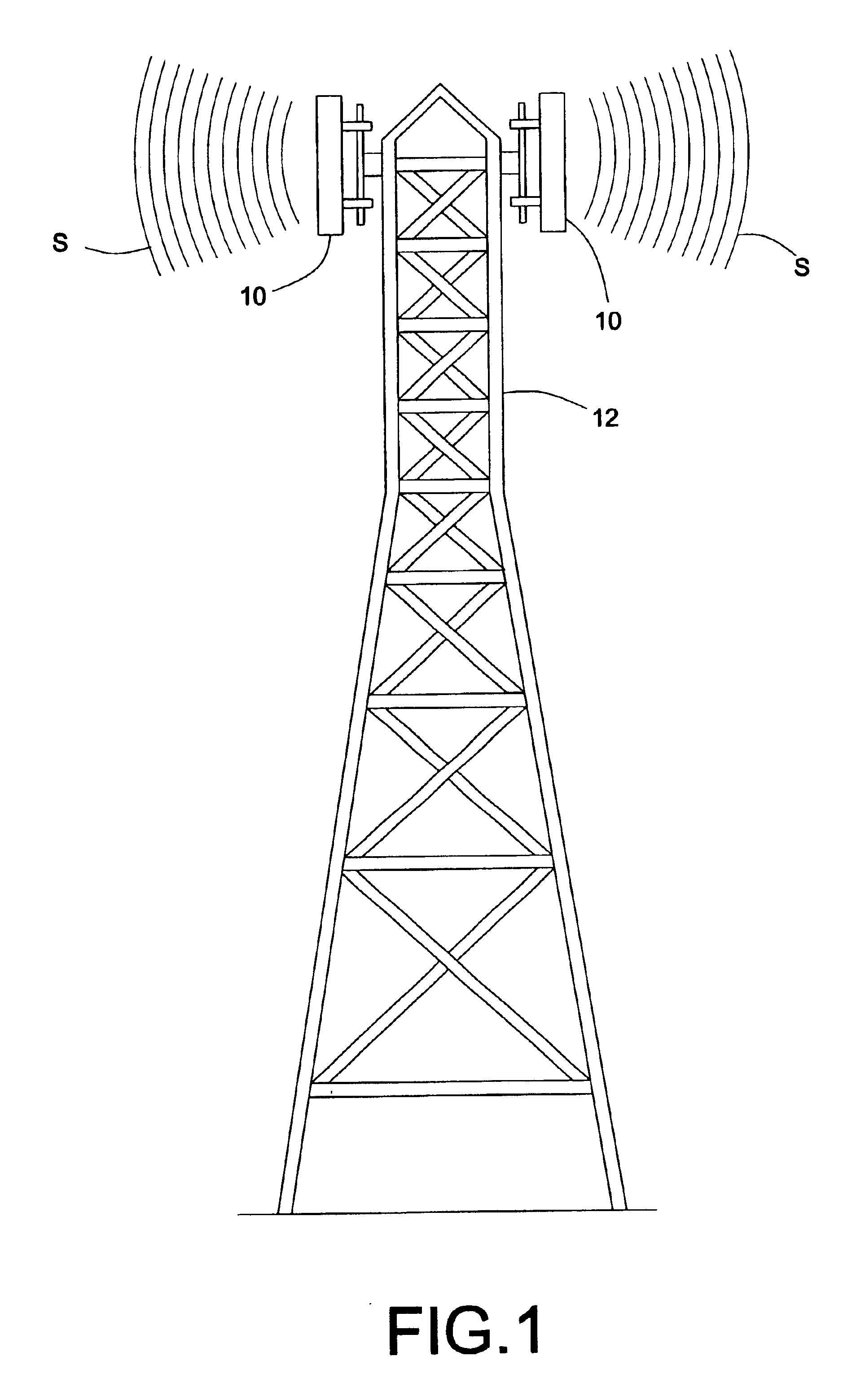
[0017]Referring to FIG. 1, there is shown a typical ground telecommunication antenna 10 installed on a high structure such as a transmission tower 12.

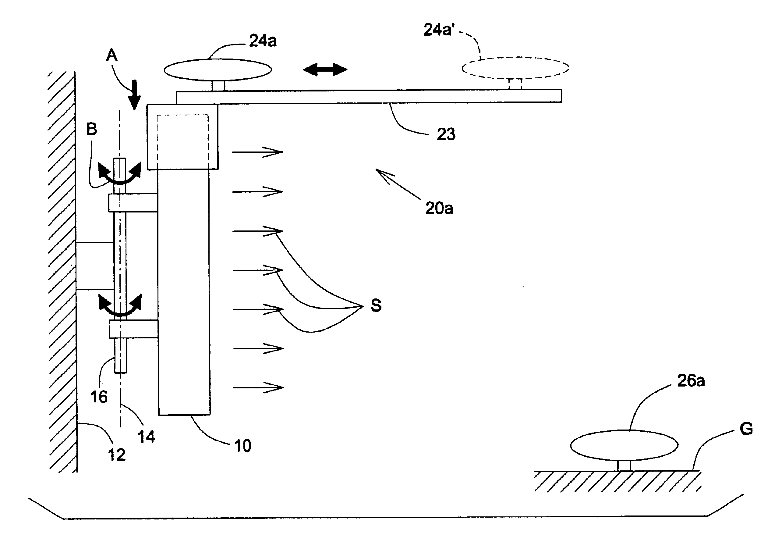
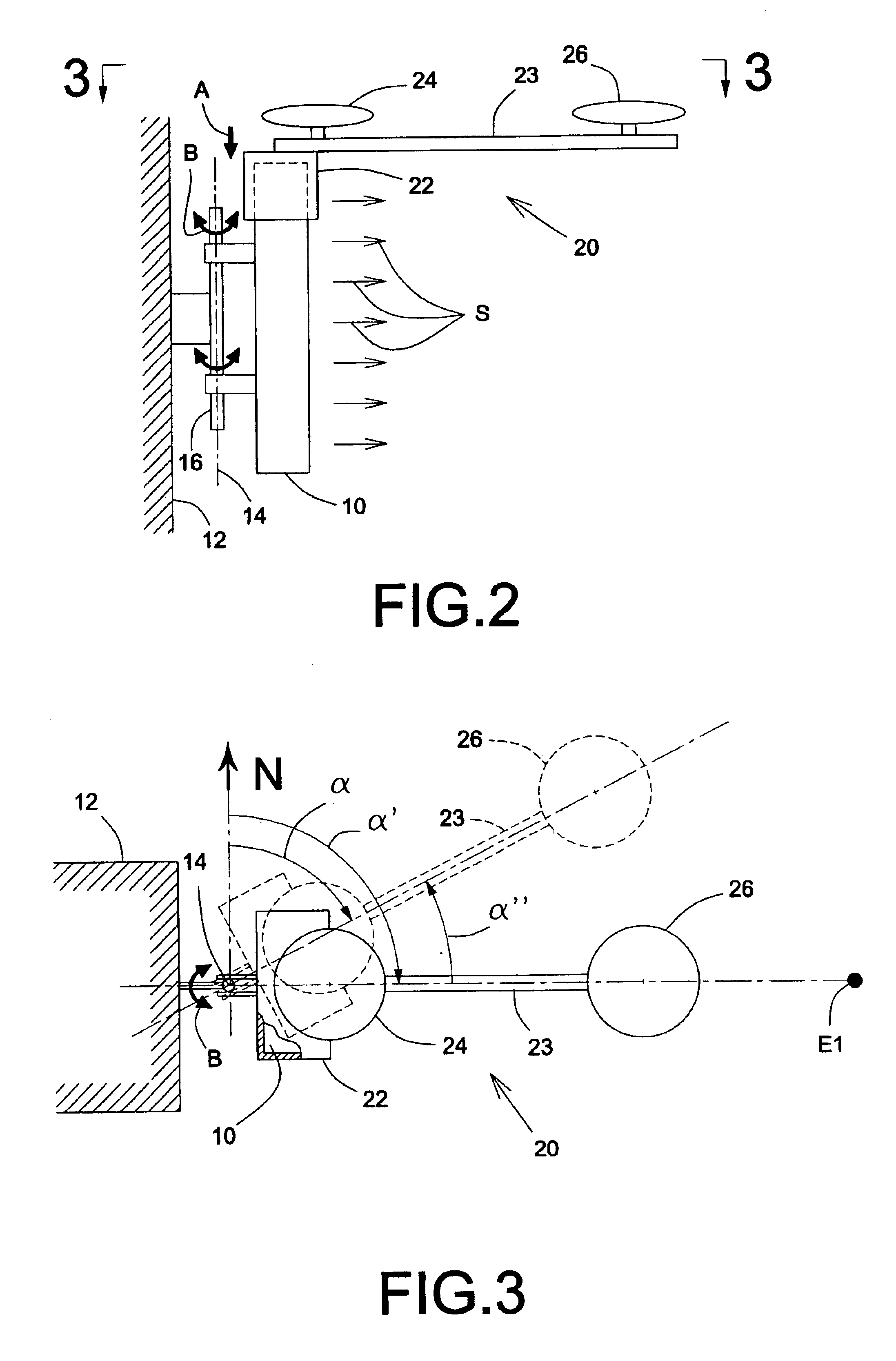
[0018]Referring to FIGS. 2 and 3, there is shown an antenna alignment system 20 in accordance with a preferred embodiment of the present invention; the alignment system 20 is typically temporarily mounted on the antenna 10 to be aligned, as schematically illustrated by arrow A of FIG. 2. The alignment system 20 includes of a universal setting frame 22, which rigidly supports a substantially horizontally positioned support arm 23 of approximately 2.5 meters long, the latter could be extended according to the alignment precision required by the client. The support arm 23 typically is a measuring device, such as a ruler, the use of which is described below. The fr...


PUM


Abstract

A method of aligning an antenna within a predetermined azimuth direction, in which the antenna is hingeably connected to a support. In response to processed positioning data received by a first global positioning system receiver dish from a global positioning satellite system, the first receiver dish being connected to the antenna and locatable at predetermined first and second positions away from the antenna, the first receiver dish determines an antenna azimuth direction and is moved from the antenna azimuth direction towards the predetermined azimuth direction so as to align the antenna.

Description

CROSS REFERENCE TO RELATED APPLICATION[0001]This application is related to U.S. provisional application for patent Ser. No. 60 / 376,199 filed on Apr. 30, 2002.FIELD OF THE INVENTION[0002]The present invention concerns an antenna, more particularly to a method of aligning the antenna within a predetermined azimuth direction.BACKGROUND OF THE INVENTION[0003]Wireless communications are now commonplace and rely on telecommunication antennae to transmit information to wireless devices such as mobile telephones including cellular, PCS, GMS and the like.[0004]For maximum broadcast area coverage, the telecommunications antennae are located at high altitudes, such as on transmission towers and hi-rise buildings. The antennae must be aligned with a reference point, especially in azimuth (within a horizontal plane), with a considerable degree of precision for optimum broadcast and reception quality in addition to achieving a maximum broadcast range. Typically, for antenna alignment, surveyors a...

Claims


Application Information

Patent Timeline
IPC IPC(8): H01Q1/12H01Q1/24H01Q1/00H01Q3/02
CPCH01Q1/125H01Q1/246H01Q1/1264
Inventor BOUCHER, CHRISTIAN
Owner 10322156 CANADA INC
Why Eureka
Try Eureka