Illuminating optical unit in image display unit, and image display unit

a technology of illumination optical unit and image display unit, which is applied in the direction of television system, printing, instruments, etc., can solve the problems of troublesome maintenance of light source, short life of light source, and limited color reproduction area, so as to suppress speckle noise and suppress image quality degradation

Inactive Publication Date: 2005-05-24
SONY CORP
View PDF6 Cites 45 Cited by
  • Summary
  • Abstract
  • Description
  • Claims
  • Application Information

AI Technical Summary

Benefits of technology

[0012]It is an object of the present invention to suppress speckle noise and suppress degradation of image quality in an image display unit such as a projection display.
[0015]According to the illuminating optical unit in an image display unit and the image display unit of the present invention, the laser beam of the P polarized light component and the laser beam of the S polarized light component are separated from each other and, in addition, the optical path difference not less than the coherence length is generated between both of the polarized light components. This makes it possible to make both of the laser beams have no correlation with each other and, therefore, to suppress speckle noise.
[0016]In the illuminating optical unit and the image display unit according to the present invention, the polarized light separation means and the optical path difference generation means may be constituted in the form of one prism. This constitution reduces the number of component parts.
[0017]The illuminating optical unit and the image display unit according to the present invention may further include a beam intensity separation means for dividing the intensity of the laser beam to form two or more laser beams parallel to each other and generating an optical path difference not less than the coherence length of the laser beam between the two or more separated laser beams. This makes it possible to separate the laser beam into a plurality of laser beams and to form the optical path difference not less than the coherence length between the optical paths of the plurality of separated laser beams. Therefore, the plurality of laser beams reach a screen at mutually different angles, which makes it possible to generate different speckle patterns and thereby to suppress further the speckle noise.
[0018]In the illuminating optical unit and the image display unit according to the present invention, the absolute value of the difference between the optical path difference generated by the optical path difference generation means and the optical path difference generated by the beam intensity separation means may be not less than the coherence length. This ensures that, even where the separation ratio in the separation by the polarized light separation means does not reach 100%, the polarized light component on one side which has not been separated and the polarized light component on one side which has been separated would not form an interference fringe, so that noise on the screen can be suppressed.
[0019]In the illuminating optical unit and the image display unit according to the present invention, the spatial modulation device may be a grating light valve. This makes it possible to display a seamless, sharp and bright image. In addition, since the grating light valve can be inexpensively manufactured by use of the micro-machine technology, the manufacturing cost of the image display unit can be lowered.

Problems solved by technology

Where such a lamp is used as a light source, however, there is the problem that the life of the light source is short and, hence, maintenance thereof is troublesome.
In addition, an optical system for picking up three primary colors of light from the white light generated from the lamp is complicated, color reproduction region is limited and light utilization efficiency is lowered.
However, where a laser light source is used as a light source for an image display unit such as the above-mentioned projection display, there occurs the problem that speckles (or speckle noise) are generated, which degraded the image quality.
However, the laser beam with a low spatial coherence lacks stability, i.e., it is liable to generate noise and the beam shape and intensity distribution thereof are liable to vary.
Thus, the laser beam with a low spatial coherence is unsuitable for use as a light source for the image display unit such as a projection display.
In the technological status at present, a visible laser beam which is stable in beam shape, intensity distribution and the like and which has a high output is generally high in spatial coherence, leading to the above-mentioned problem of speckle noise.

Method used


Image

  • Illuminating optical unit in image display unit, and image display unit
  • Illuminating optical unit in image display unit, and image display unit
  • Illuminating optical unit in image display unit, and image display unit

Examples


Embodiment Construction

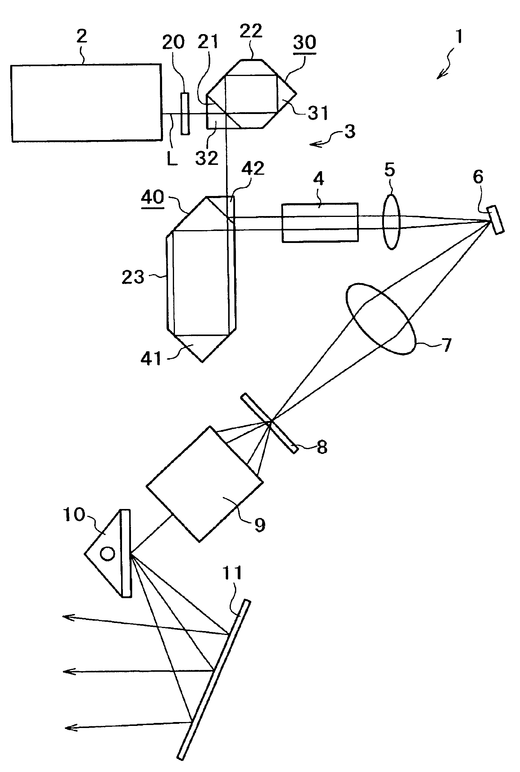
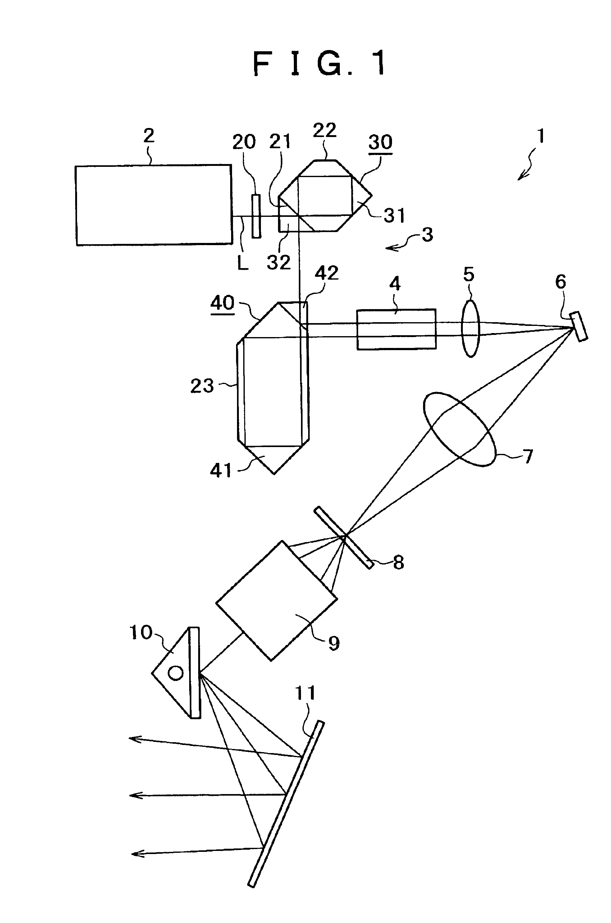
[0031]The present invention pertains to an image display unit for displaying an image by irradiating a spatial modulation device with a laser beam and modulating the laser beam based on an image signal inputted to the spatial modulation device and to an illuminating optical unit for use therein. Examples of the image display unit include front projection type or rear projection type laser displays and, further, a wide variety of image display units including printing and recording, such as a laser beam printer, an apparatus for recording images onto a movie film based on digital image data, and so on.

[0032]Examples of the spatial modulation device include a liquid crystal, a DMD and the like, in addition to the above-mentioned GLV.

[0033]Now, embodiments of the present invention will be described below, referring to the accompanying drawings.

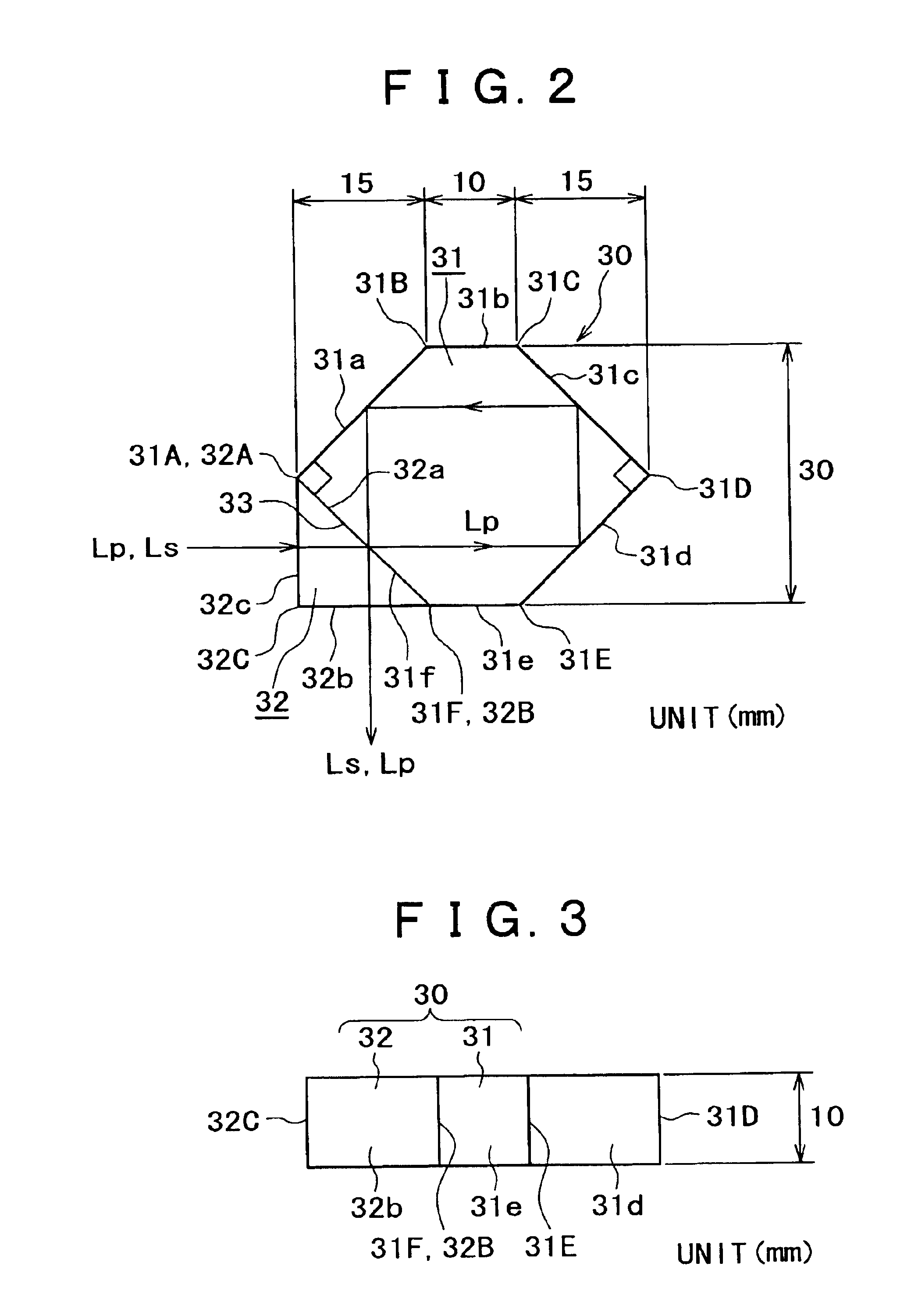
[0034]FIGS. 1 to 10 illustrate embodiments of the present invention in which the present invention is applied to an illuminating optical unit in...


PUM

PropertyMeasurementUnit
coherence lengthaaaaaaaaaa
wavelengthaaaaaaaaaa

Abstract

Disclosed is an illuminating optical unit in an image display unit for displaying an image by irradiating a GLV (spatial modulation device) with a laser beam and modulating the laser beam based on an image signal inputted to the GLV, which includes a polarized light rotation means for equally dividing a polarized light component of the laser beam into a P polarized light component and an S polarized light component, a polarized light beam splitter for separating from each other the P polarized light component and the S polarized light component equally divided by the polarized light rotation means, and an optical path difference generation means for generating an optical path difference not less than the coherence length of the laser beam between the laser beam of the P polarized light component and the laser beam of the S polarized light component.

Description

BACKGROUND OF THE INVENTION[0001]The present invention relates to an illuminating optical unit in an image display unit for displaying an image by use of light modulated by a spatial modulation device, and to the image display unit. More particularly, the invention relates to a technology for enhancing the quality of an image.[0002]As a form of image display unit, hitherto there has been proposed a projection display in which a screen is irradiated with a light beam modulated by a spatial modulation device, such as a liquid crystal panel, a DMD (Digital Micromirror Device), etc., to display an image on the screen. In such a projection display, conventionally, a lamp, such as a metal halide lamp, a halogen lamp and a xenon lamp, has been used as a light source.[0003]Where such a lamp is used as a light source, however, there is the problem that the life of the light source is short and, hence, maintenance thereof is troublesome. In addition, an optical system for picking up three pri...

Claims


Application Information

Patent Timeline
Patent Type & Authority Patents(United States)
IPC IPC(8): G02B26/08G02B5/18G02B27/28G02B27/48H04N5/74G02B27/18G03B21/00H04N9/31
CPCG02B5/1828G02B26/0808H04N9/3129G02B27/48H04N5/7416G02B27/283
Inventor KIKUCHI, HIROKI
Owner SONY CORP
Why Eureka
Try Eureka