
Floating-gate analog circuit

a floating-gate analog circuit and logic gate technology, applied in the field of analog circuits, can solve the problems of limited implementation of programmable devices in the analog domain, difficulty in reconfigurable integrated circuits, and unnecessary design flexibility down to logic gates

Inactive Publication Date: 2005-05-24
GEORGIA TECH RES CORP
View PDF8 Cites 30 Cited by
  • Summary
  • Abstract
  • Description
  • Claims
  • Application Information

AI Technical Summary

Benefits of technology

[0011]The present invention provides methods and systems for configuring a floating-gate transistor device to perform a computational function upon an input signal that is coupled into a floating-gate of the floating gate field-effect transistor, wherein the computational function is de

Problems solved by technology

In many situations, this level of design flexibility down to a logic gate is unnecessary.
Accommodating such a variety of values in such a variety of discrete components, to cater to flexible design of analog circuits inside a programmable / reconfigurable integrated circuit is a challenging task.
This condition has led to limited implementations of programmable devices in the analog domain.
On the other hand, this approach has proved very limiting to analog designers desirous of using an FPAA to create a design at a primitive level extending down to a transistor.
While digital memory devices are very popular and widely available, analog memory devices are relatively obscure and are limited in their performance.
Typically, analog memory devices have been manufactured as standalone devices, and where integrated into FPAAs have provided limited performance characteristics.

Method used


Image

  • Floating-gate analog circuit
  • Floating-gate analog circuit
  • Floating-gate analog circuit

Examples


Embodiment Construction

[0026]While the description below refers to certain exemplary embodiments, it is to be understood that the invention is not limited to these particular embodiments. On the contrary, the intent is to cover all alternatives, modifications and equivalents included within the spirit and scope of the invention as defined by the appended claims. Also, the terminology used herein is for the purpose of description and not of limitation.

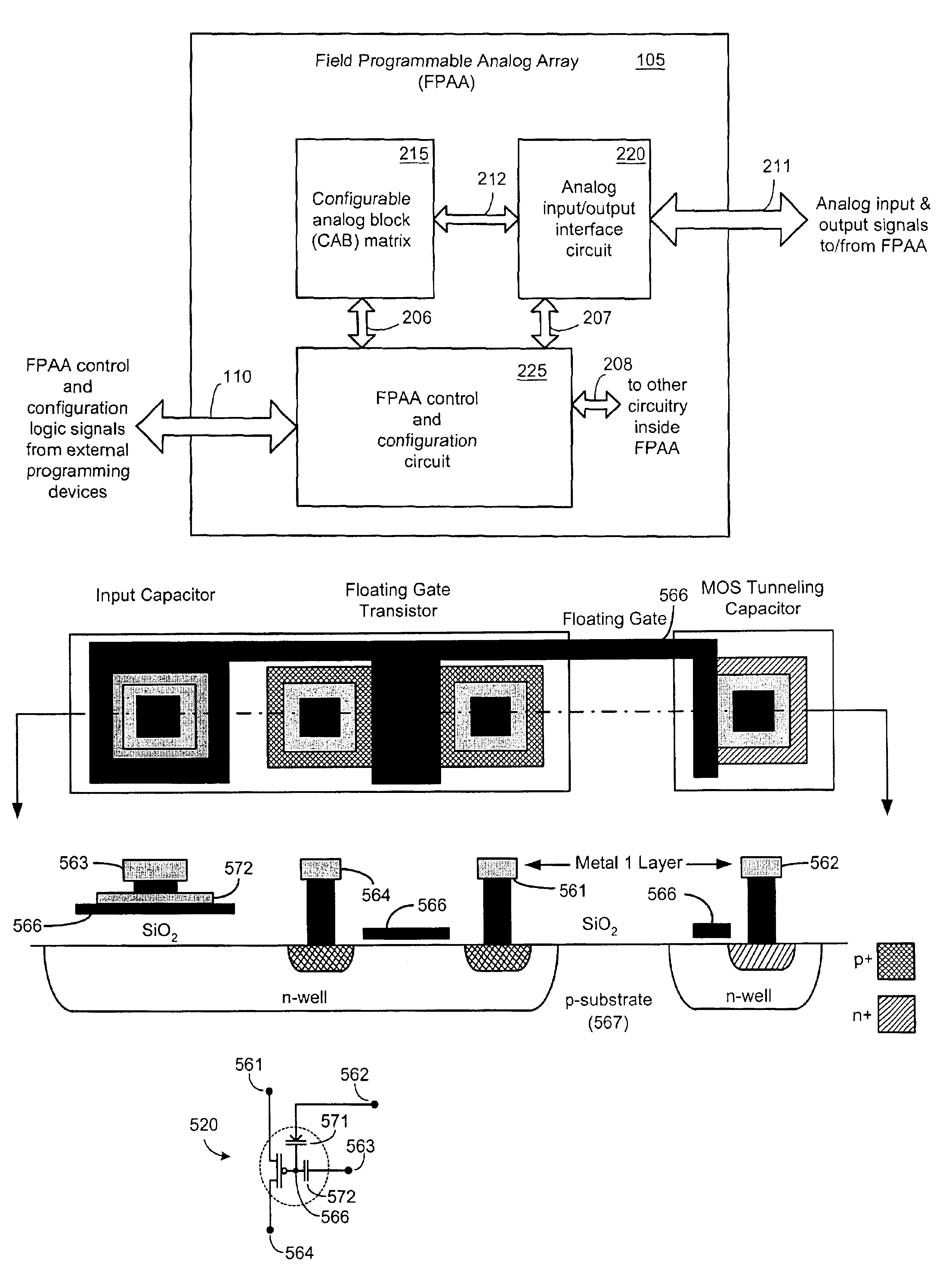
[0027]The description of several components of this invention has been carried out using figures drawn in a hierarchical fashion, wherein each progressive figure provides greater details of a component than was provided in an earlier figure.

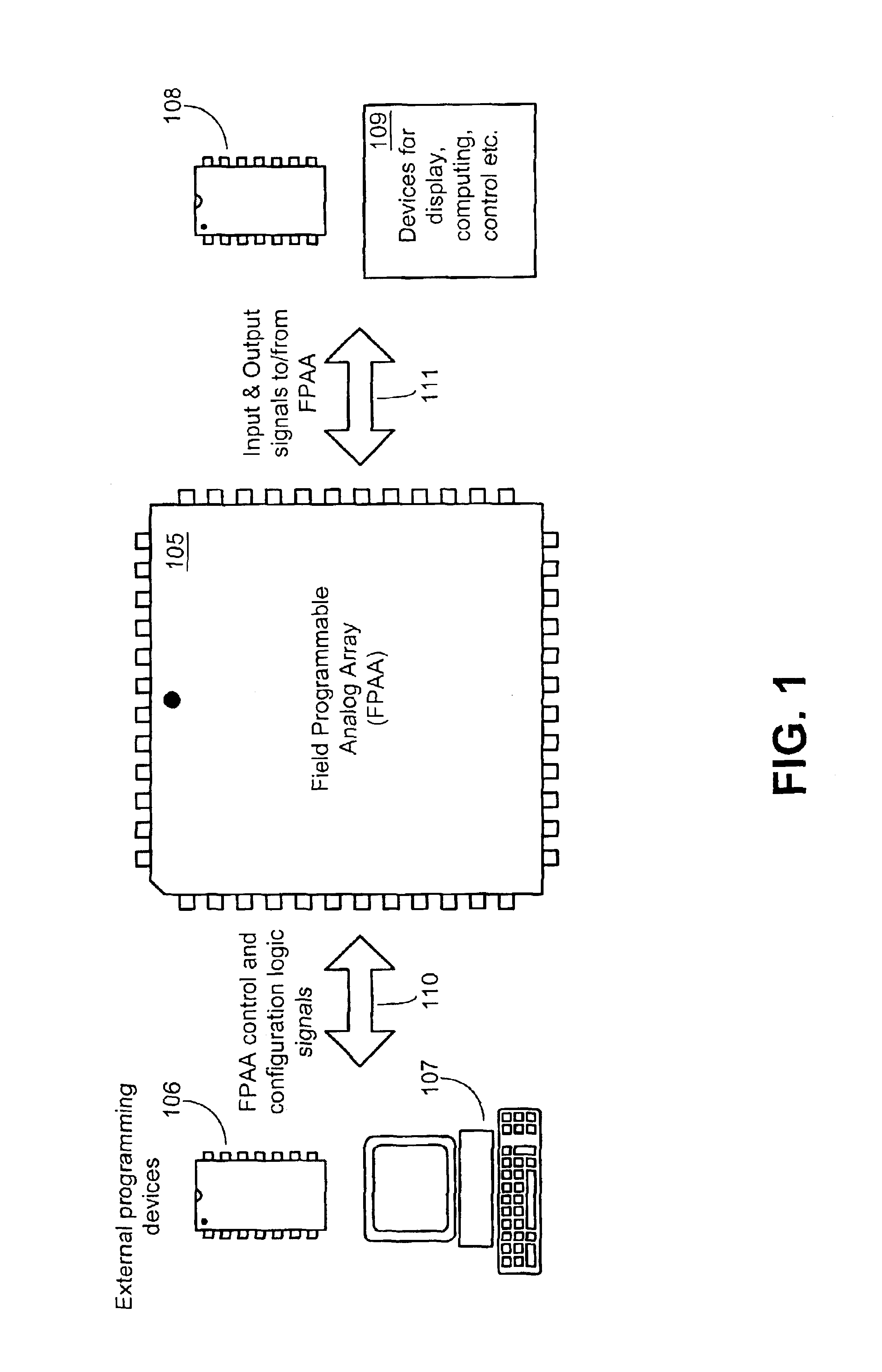
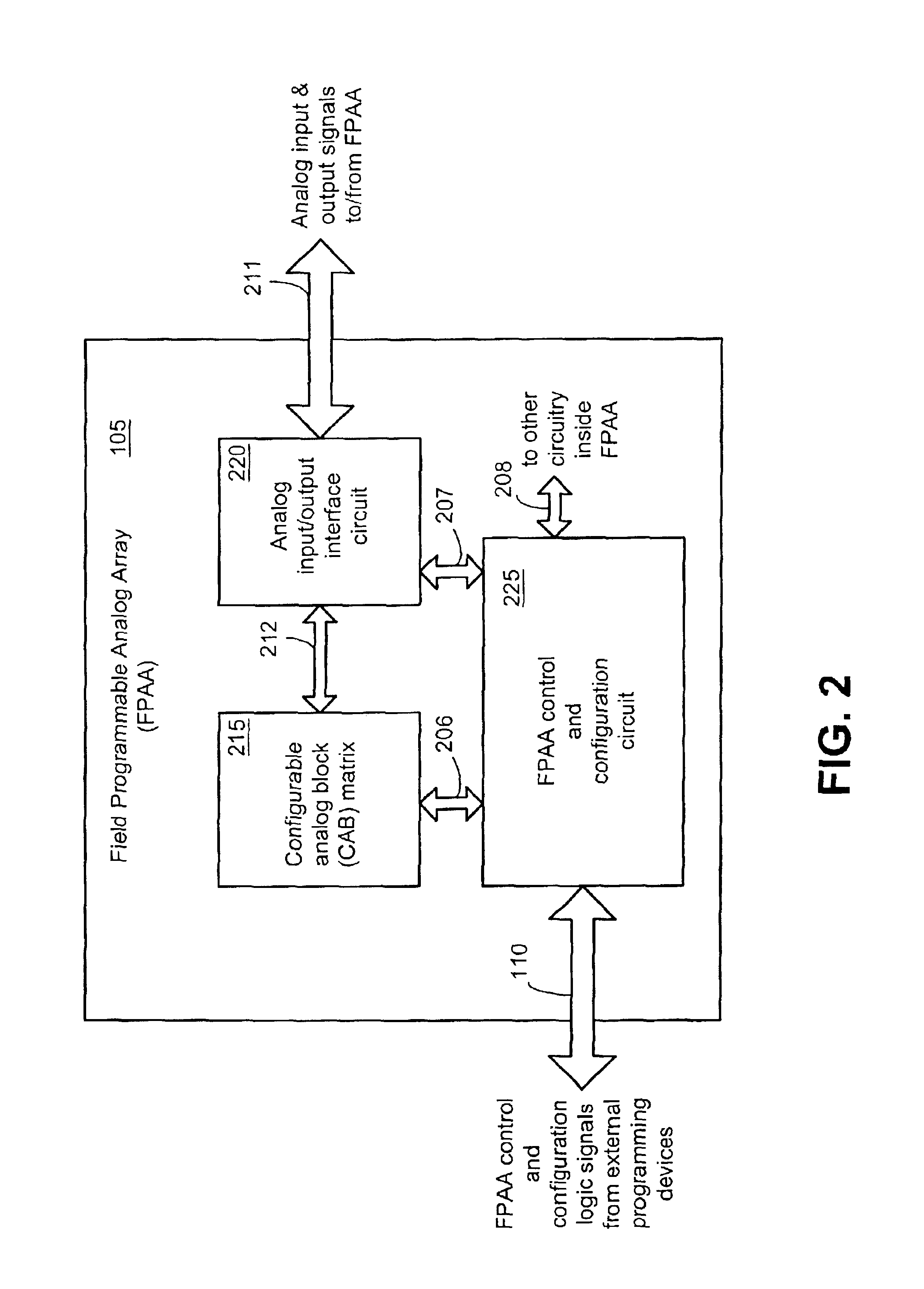
[0028]FIG. 1 illustrates a field programmable analog array (FPAA) 105 incorporating the invention, implemented in an exemplary integrated circuit package that is programmable using one or more external programming devices such as programming devices 106 and 107. Programming device 106 is an integrated circuit, which for ex...


PUM


Abstract

In one exemplary embodiment, a programmable analog array (PAA) contains a configurable analog matrix having two floating-gate field effect transistors (FETs). Also contained in the PAA is an interconnect circuit that is programmable to configure the configurable analog matrix to operate in one or more of several matrix modes. A few examples of such matrix modes include a switching matrix mode, a memory matrix mode, and a computing matrix mode. In an exemplary method of configuring the PAA. PAA, the the method includes programming an interconnection, for example, between a first terminal of the first floating-gate FET and a first terminal of the second floating-gate FET. The method further includes programming an interconnection, for example, between a gate terminal of the first floating-gate FET and a fixed voltage source, for setting a floating gate charge on the first floating-gate FET.

Description

CROSS REFERENCE TO RELATED APPLICATIONS[0001]This application claims the benefit of U.S. Provisional Patent Application Ser. No. 60 / 366,714 filed Mar. 22, 2002, which is incorporated herein by reference in its entirety.STATEMENT REGARDING FEDERALLY SPONSORED RESEARCH OR DEVELOPMENT[0002]The U.S. government may have a paid-up license in this invention and the right in limited circumstances to require the patent owner to license others on reasonable terms as provided for by the terms of Grant No. EIA-0083 172 awarded by the National Science Foundation of the U.S.FIELD OF THE INVENTION[0003]The present invention generally relates to the field of analog circuits. More specifically it relates to programmable analog arrays that can be programmed at a transistor level.BACKGROUND AND PRIOR ART[0004]Hardware design of a digital logic circuit is often initiated by evaluating a prototype circuit that is programmed into a reconfigurable device such as a field programmable gate array (FPGA) or a...

Claims


Application Information

Patent Timeline
IPC IPC(8): H01L29/76G11C27/00H01L29/66G06G7/12H01L21/82H01L21/8247H01L27/115H01L29/788H01L29/792H03F1/32H03F3/08H03F3/45H03K19/177H04L
CPCG06G7/12G11C27/005H03F1/3211H03F1/3241H03F3/082H03K19/1778H03K19/17732H03K19/1776H03F3/45183H03F2200/174H03F2203/45121G06N3/065H03K19/177
Inventor DUGGER, JEFFERY DONHALL, TYSON S.HASLER, PAULANDERSON, DAVID V.SMITH, PAUL D.KUCIC, MATTHEW RAYMONDBANDYOPADHYAY, ABHISHEK
Owner GEORGIA TECH RES CORP
Learn More