Latch type sense amplifier method and apparatus

Inactive Publication Date: 2005-05-24
IBM CORP +2
View PDF2 Cites 4 Cited by
  • Summary
  • Abstract
  • Description
  • Claims
  • Application Information

AI Technical Summary

Benefits of technology

[0004]The present invention relates in general to minimizing power and circuit layout requirements for circuitry required in a high frequency memory sense amplifier read-out path.

Problems solved by technology

When operating in conjunction with a high frequency pipeline SRAM, such a dynamic output signal is hard to catch and distribute.
Further, transmission delay concerns require that the SA be physically close to the read-out latch in these prior art circuits.
Such a dotted OR circuit consumes relatively large amounts of power, especially when operating in the dynamic mode, and further occupies a large amount of space on an integrated circuit chip.

Method used


Image

  • Latch type sense amplifier method and apparatus
  • Latch type sense amplifier method and apparatus
  • Latch type sense amplifier method and apparatus

Examples


Embodiment Construction

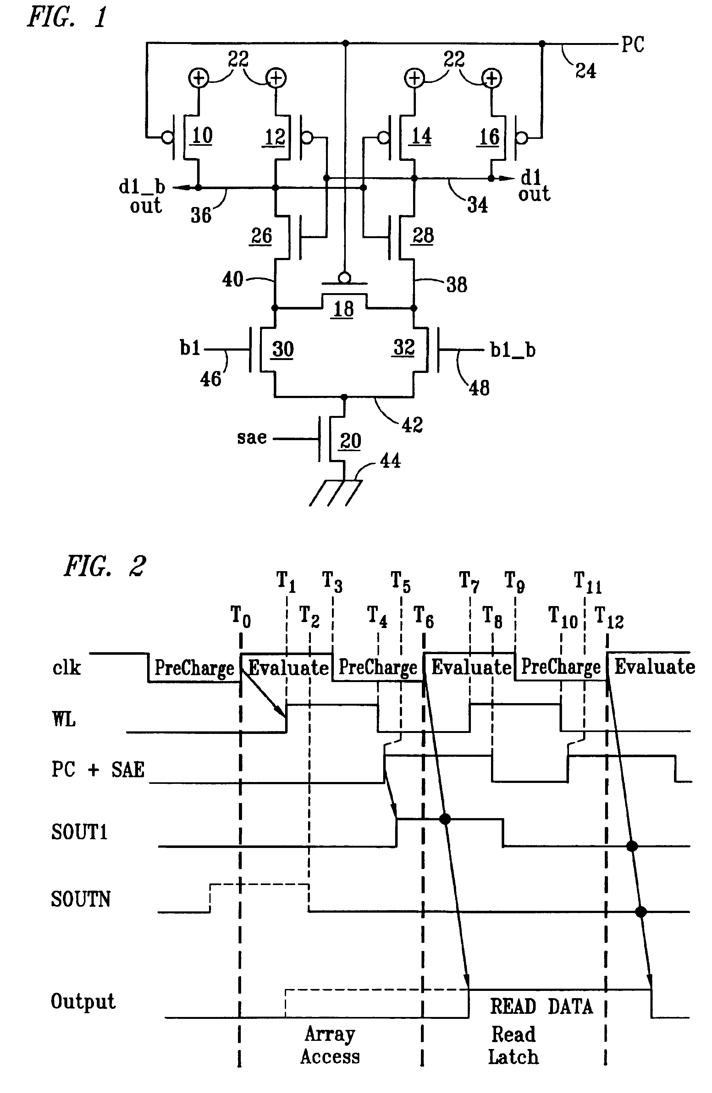
[0009]In FIG. 1, a plurality of P type or P channel FET (field effect transistors) 10, 12, 14, 16, and 18 are shown. FETs 10, 12, 14, and 16 each have their source terminal connected to a positive voltage designated as 22. The gate of each of FETs 10, 16 and 18 are connected to a lead 24 that provides a PC (pre-charge) signal. This signal may be identical to that shown as an SAE (SA enable) and a PC signal in FIG. 2. An N type FET 20 is shown having the SAE signal of FIG. 2 supplied to the gate thereof. Further N type or N channel FET transistors are labeled as 26, 28, 30, and 32. As known to those skilled in the art, P type FETs act as closed switches or, in other words, turn ON to allow current flow from source to drain when the gate terminal is at a low potential with respect to the source. When the gate is open, or the same potential as the source, the FET is OFF or, in other words, does not conduct electricity. On the other hand, N type FETs act as closed or ON switches to allo...


PUM


Abstract

Disclosed is an apparatus for and a method of overcoming signal delay problems in a read-out path occurring in connection with pipelined memory circuits. A latch type sense amplifier (SA) is used to receive the memory cell logic levels during a pre-charge state in a cycle prior to read-out. Thus, the SA may quickly provide an output signal during a read latch clock cycle. The SA output is passed through a dynamically enabled logic circuit to a latch circuit for holding the receiving logic value for use in the next clock cycle.

Description

TECHNICAL FIELD[0001]The present invention relates in general to capturing the output of a memory cell sense amplifier operating in conjunction with a high frequency circuit such as pipelined memory.BACKGROUND[0002]Typical prior art SAs (Sense Amplifiers) used in conjunction with SRAM (Static Random Access Memory) provide only dynamic output signals. Thus the output needs to be captured within the period of the read cycle by a read-out latch. When operating in conjunction with a high frequency pipeline SRAM, such a dynamic output signal is hard to catch and distribute. Further, transmission delay concerns require that the SA be physically close to the read-out latch in these prior art circuits. When applicable, multiple SA outputs may be collected by a dynamic dotted OR circuit. Such a dotted OR circuit consumes relatively large amounts of power, especially when operating in the dynamic mode, and further occupies a large amount of space on an integrated circuit chip. The alternative...

Claims


Application Information

Patent Timeline
IPC IPC(8): G11C7/10G11C7/06
CPCG11C7/065G11C7/1069G11C7/1051
Inventor ASANO, TORUDHONG, SANG HOONAKAZATO, TAKAAKITAKAHASHI, OSAMU
Owner IBM CORP
Why Eureka
Try Eureka