
Integrated active noise attenuation system and fluid reservoir

Inactive Publication Date: 2005-05-24
SIEMENS VDO AUTOMOTIVE
View PDF32 Cites 7 Cited by
  • Summary
  • Abstract
  • Description
  • Claims
  • Application Information

AI Technical Summary

Benefits of technology

[0006]The present invention comprises an active noise attenuation system. The active noise attenuation system has a speaker in proximity to an air intake and serves to emit an output for attenuating noise from the air intake. A control unit controls the speaker, modulating its output to thereby reduce noise. The speaker is housed in a housing that has a first chamber and a second chamber. The first chamber houses the speaker while the second chamber houses the fluid reservoir for fluids such as engine coolant or windshield wiper fluid. By combining the two chambers into a single housing, the amount of space required by the active noise attenuation system and the fluid reservoir is thereby reduced. Moreover, the number of parts within the engine compartment is also reduced.
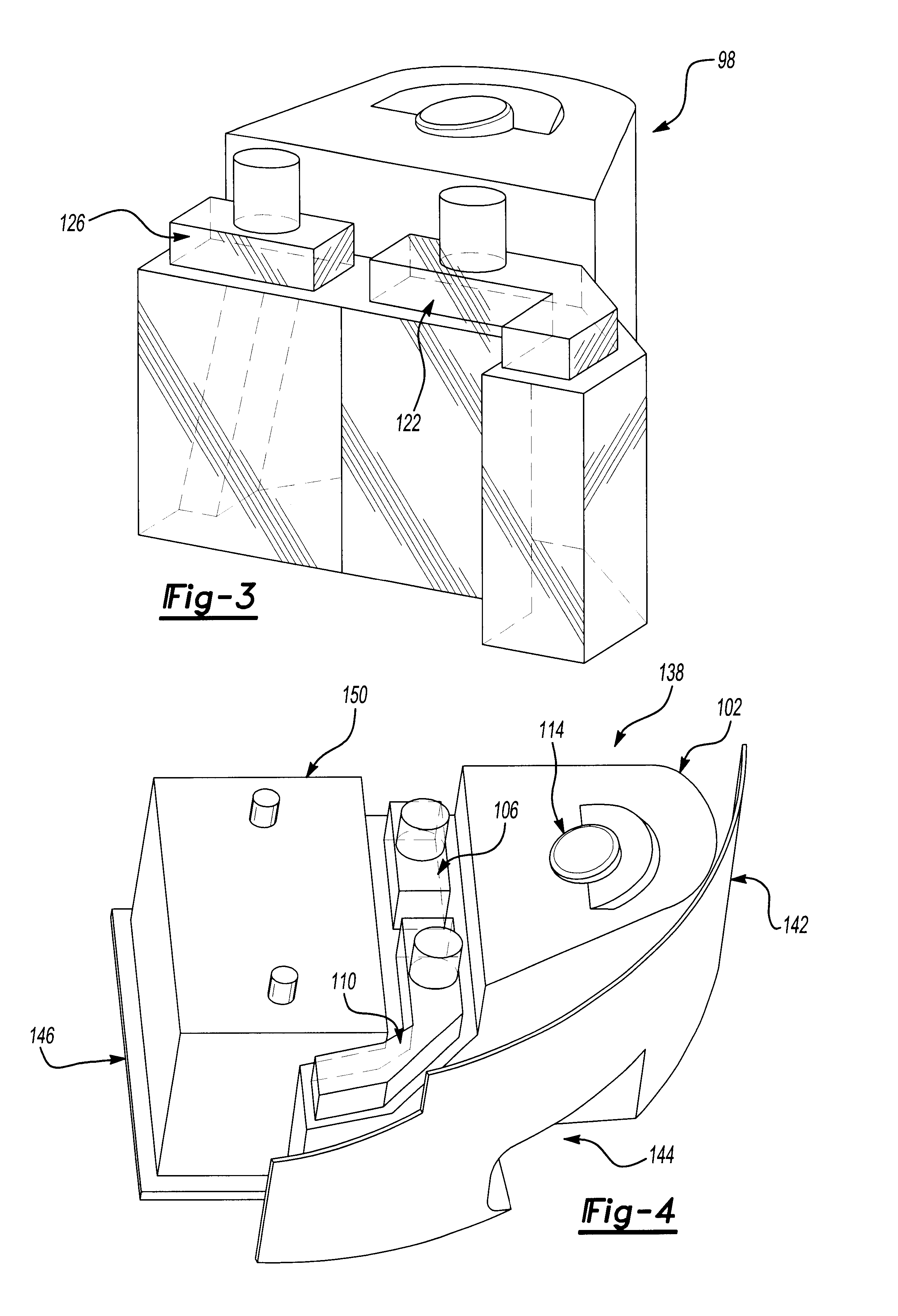
[0007]The fluid reservoir may be in communication with the windshield wiper system or an engine cooling system. Moreover, a third fluid storage chamber may be used so that the unit may accommodate both fluid for the windshield wiper system and fluid for the engine cooling system. A plate may be disposed within the fluid volume to limit the movement of fluid contained therein. Also, each fluid reservoir may have a transparent sight glass or have a portion of the volume be sufficiently transparent to allow viewing of the fluid levels within the reservoir. By locating the active noise attenuation system near these fluid reservoirs, the unit may also be combined with a battery tray which is typically located within the same vicinity. The unit may also be combined with tubing from the air induction system and also be combined with an air filter. The invention may thus offer a single housing for a significant number of engine components, reducing the amount of space and parts required by them.

Problems solved by technology

Such noise frequently emanates from the engine, travels through the air induction system and emanates out of the mouth of the air intake into the passenger compartment.
In one such system, a control unit, such as a digital signal processor, obtains data from the vehicle engine, creates a predictive amount of engine noise, and thereby generates the appropriate cancellation signals based on the results of this model.
The engine compartments of vehicles are cramped and offer little additional space for an active noise attenuation system.
Accordingly, the necessity of locating an active noise attenuation system in proximity to the air intake in the confined space of an engine compartment presents design challenges.

Method used


Image

  • Integrated active noise attenuation system and fluid reservoir
  • Integrated active noise attenuation system and fluid reservoir
  • Integrated active noise attenuation system and fluid reservoir

Examples


Embodiment Construction

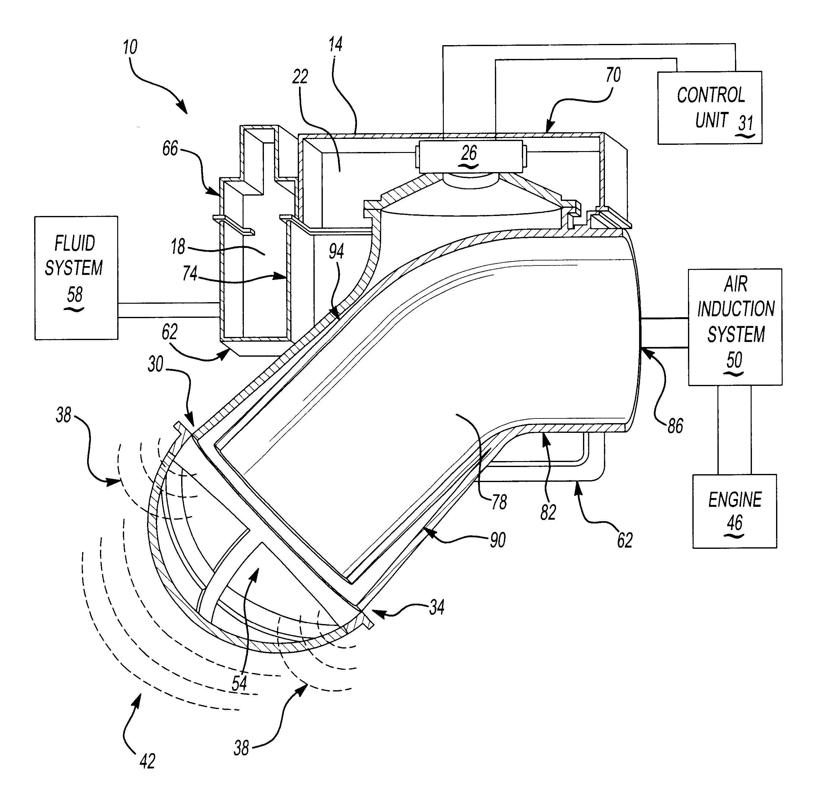
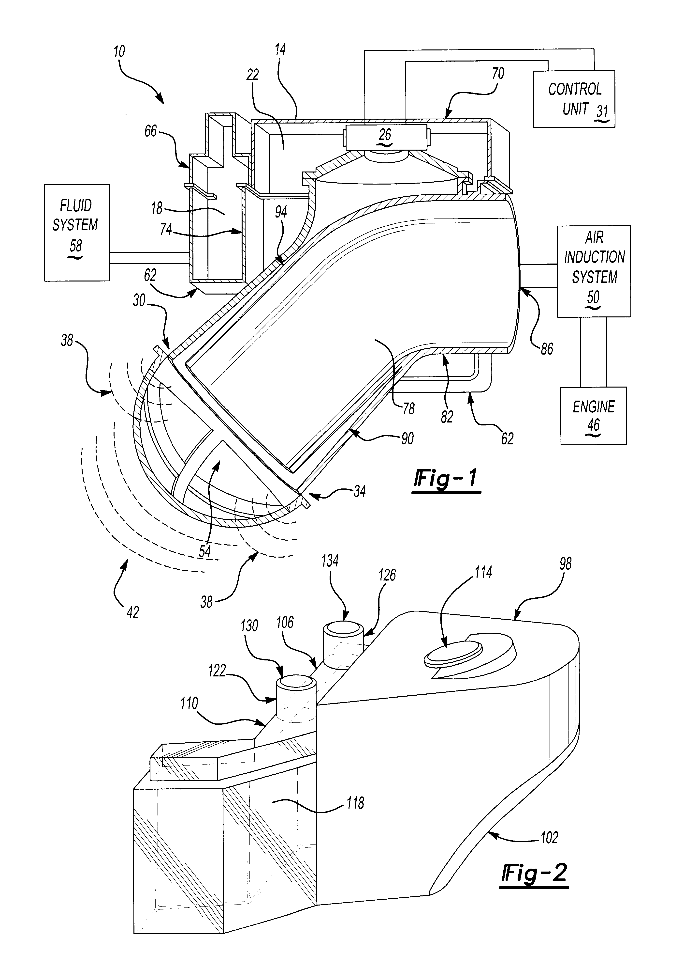
[0019]FIG. 1 illustrates invention 10. As shown, housing 14 defines at least two volumes. One volume 22 houses speaker 26 as commonly used for a noise attenuation system. Speaker 26 is controlled by control unit 31 and generates a noise canceling sound which flows out of inlet 30 and inlet 34. Thus, as known, canceling sound 38 is propagated out of two inlets to attenuate engine noise 42 originating from engine 46, passing through air induction system 50, and out air intake 54.

[0020]By locating speaker 26 and speaker chamber 26 near the liquid storage chambers of an engine cooling system or a fluid reservoir, housing 14 maybe formed to integrate the fluid reservoir of fluid system 58. Accordingly housing 14 may comprise volume 18 acting as a liquid storage chamber, which is in fluid communication with fluid system 58, such as an engine cooling system or a windshield wiper fluid system, and volume 22 which serves as an acoustic chamber for speaker 26. Volume 22 may be formed acoustic...


PUM


Abstract

An active noise attenuation system (10) comprises a speaker (26) in communication with a flow body (78). The speaker (26) emits an output for attenuating noise from the flow body (78). A control unit (31) communicates with the speaker (26) and controls the output. A housing (14) has one volume (18) acting as a liquid storage chamber and another volume (22) acting as a speaker chamber.

Description

[0001]This application claims priority to Provisional Patent Application Ser. No. 60 / 276,211 filed on Mar. 15, 2001, Provisional Patent Application Ser. No. 60 / 270,769 filed on Feb. 22, 2001, and is a continuation-in-part of U.S. Nonprovisional application Ser. No. 09 / 931,394 filed on Aug. 16, 2001.BACKGROUND OF THE INVENTION[0002]This invention relates to a method and system of noise attenuation around an air induction assembly.[0003]Manufacturers have employed active and passive methods to reduce engine noise within the passenger compartment. Such noise frequently emanates from the engine, travels through the air induction system and emanates out of the mouth of the air intake into the passenger compartment. Efforts have been made to reduce the amount of engine noise traveling through the air induction system. These efforts include the use of both passive devices such as expansion chambers and helmholtz resonators and active devices involving anti-noise generators.[0004]Active sys...

Claims


Application Information

Patent Timeline
IPC IPC(8): B60K13/00B60K13/02F02M35/12G10K11/178G10K11/00
CPCB60K13/02G10K11/1788F02M35/125G10K2210/107G10K2210/121G10K2210/3031G10K2210/3214G10K2210/3217G10K2210/3229G10K2210/1282G10K11/17873G10K11/17857
Inventor VANDERVEEN, JAMES K.XIA, ZHOUXUAN
Owner SIEMENS VDO AUTOMOTIVE
Learn More