Developing device having a developer forming a magnet brush

Inactive Publication Date: 2005-05-24
RICOH KK
View PDF31 Cites 37 Cited by
  • Summary
  • Abstract
  • Description
  • Claims
  • Application Information

AI Technical Summary

Benefits of technology

[0019]It is a first object of the present invention to provide a developing device capable of reducing, when applied to the medium-speed image forming apparatus whose image carrier moves at the linear velocity of 100 mm/sec or

Problems solved by technology

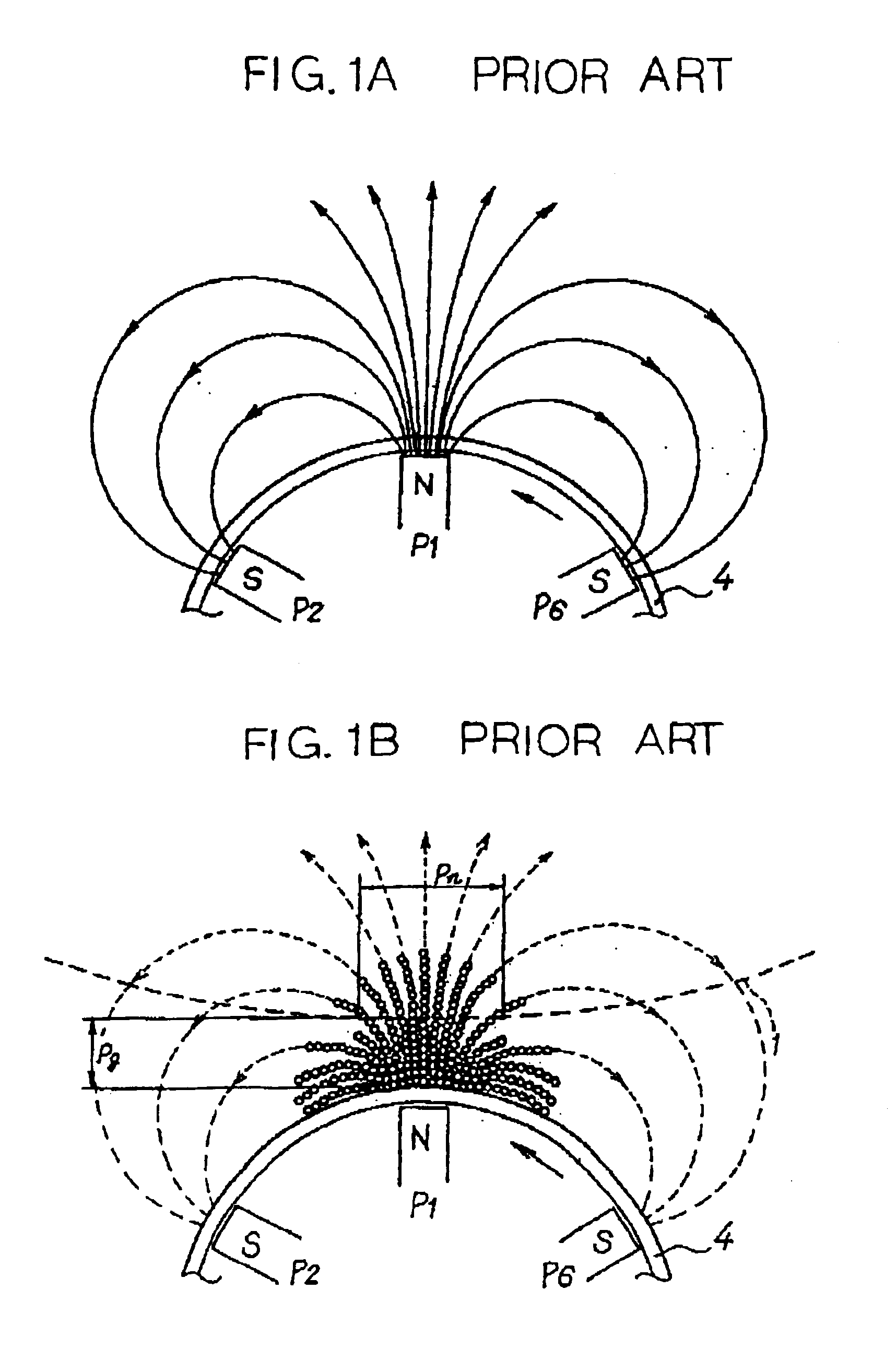
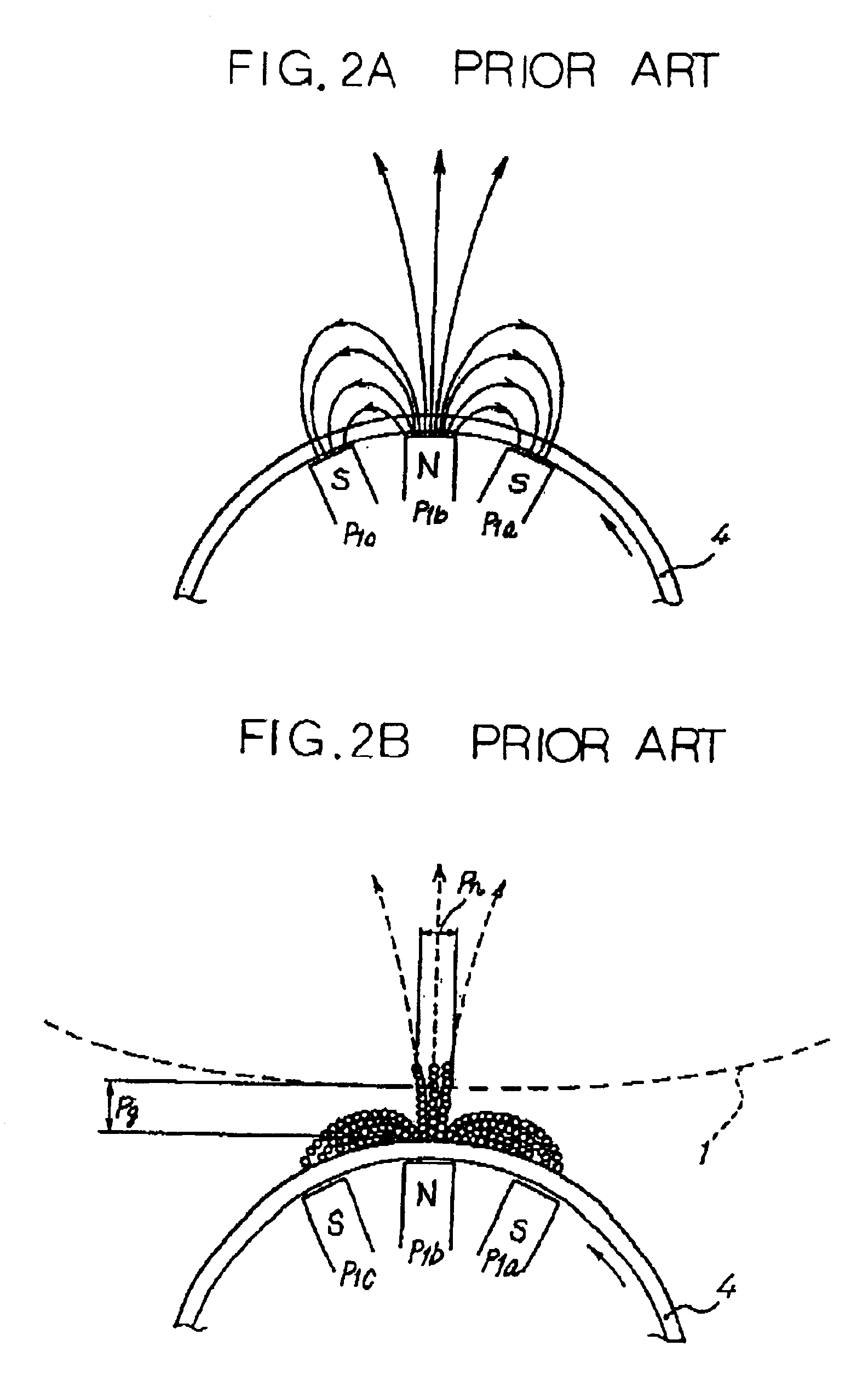
However, when the distance is reduced, it is likely that the trailing edge of a black or halftone solid image is lost or that the reproducibility of thin lines is lowered, degrading image quality.
It follows that toner drift is more conspicuous on the former brush chains than on the latter brush chains and reduces the number of toner grains present on the individual carrier grain, thereby reducing the toner feeding ability.
This is presumably the cause of the omission of the trailing edge and the degradation of thin line reproducibility.
As a result, carrier grains forming the magnetic brush are apt to part from the magnet brush due to, e.g., a shock to occur when the magnet brush contacts the image carrier, flying out of the developing device.
The carrier grains deposited on the image carrier disturb an image or cause the dots

Method used


Image

  • Developing device having a developer forming a magnet brush
  • Developing device having a developer forming a magnet brush
  • Developing device having a developer forming a magnet brush

Examples


first embodiment

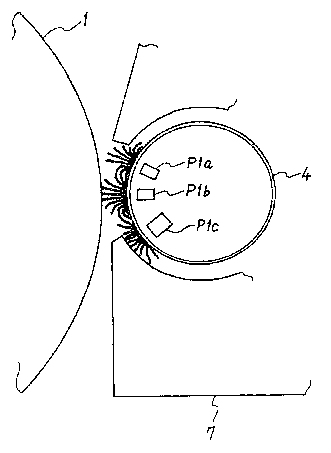
[0059]A first embodiment of the present invention, which is mainly directed toward the first object stated earlier, will be described with reference to FIG. 4. As shown, the laser printer includes a photoconductive drum or image carrier 1 rotatable in a direction indicated by an arrow A. While the drum 1 is in rotation, a charge roller or charging means 50 uniformly charges the surface of the drum 1 in contact with the drum 1. Subsequently, an optical writing unit or latent image forming means 51 scans the charged surface of the drum 1 in accordance with image data to thereby form a latent image on the drum 1. The charge roller 50 and optical writing unit 51 may, of course, be replaced with any other suitable charging means and latent image forming means, respectively.

[0060]A developing device or developing means 2, which will be described specifically later, develops the latent image to thereby produce a corresponding toner image. An image transferring unit or image transferring me...

experiment 1

[Experiment 1]

[0115]In the developing device 2 used in Experiment 1 to be described, the attenuation ratio of the normal flux density is 40% or above while the amount of developer fed is between 65 mg / cm2 and 95 mg / cm2, so that the magnet brush is short and dense, as stated earlier. It is therefore necessary to cause the sleeve 4 to move at a linear velocity 1.1 times to 3.0 times, in practice about 1.5 times to about 2.0 times, higher than the linear velocity of the drum 1, as measured at the developing zone, thereby maintaining high image quality. However, an increase in the linear velocity of the sleeve 4 brings about the carrier deposition problem. In light of this, Experiment 1 was conducted to determine a relation between the saturation magnetization value of the carrier and the carrier deposition on the drum 1.

[0116]In Experiment 1, the toner T and each of the carriers C1 through C3 were mixed to prepare two developers having a toner content of 5 wt % each. In the developing ...

experiment 2

[Experiment 2]

[0122]The toner T and each of the carriers C4 and C5 were mixed together to prepare two developers having a toner content of 5 wt %. Again, the laser printer with the developing device 2 was operated to output ten prints with each of the two developers. The prints were then estimated as to the number of white spots for a single print.

[0123]FIG. 15 lists the results of Experiment 2. As shown, when the developer containing the carrier C1 with a static resistance of 16.2 log Ω was used, the mean number of white spots for a single print was thirty-eight point three. By contrast, the mean number of white spots for a single print was seven point nine when the developer containing the carrier C4 with 12.4 log Ω was used or ten point five when the developer containing the carrier C5 with 13.8 log Ω was used. By extended studies, we found that when the static resistance was as low as 12 log Ω or above, but 14 log Ω or below, carrier deposition on the drum 1 was less conspicuous...


PUM


Abstract

In a developing device having a developing zone where an image carrier and a developer carrier face each other, the developer carrier carrying a developer thereon moves at a linear velocity of 150 mm/sec or above, but below 500 mm/sec. The amount of the developer conveyed to the developing zone by the developer carrier is between 65 mg/cm2 and 95 mg/cm2. A magnetic flux generated on the developer carrier in the developing zone by a magnetic pole has a flux density having an attenuation ratio of 40% in the direction normal to the developer carrier. The flux density in the direction normal to the developer carrier, as measured on the surface of the developer carrier, is between 100 mT and 200 mT. Magnetic grains, which constitute the developer together with toner grains, have a saturation magnetization value of 40×10−7×4 πWb·m/kg or above, but below 50×10−7×4 πWb·m/kg.

Description

BACKGROUND OF THE INVENTION[0001]1. Field of the Invention[0002]The present invention relates to a developing device for a copier, printer, facsimile apparatus or similar image forming apparatus and an image forming apparatus using the same. More particularly, the present invention relates to a developing device of the type causing a developer to form a magnet brush on a developer carrier in a developing zone where the developer carrier faces an image carrier to thereby develop a latent image formed on the image carrier, and an image forming apparatus using the same.[0003]2. Description of the Background Art[0004]It is a common practice with an electrophotographic, electrostatic or similar image forming apparatus to form a latent image on a drum, belt or similar image carrier in accordance with image data and develop it with a developing device for thereby producing a corresponding toner image. Today, a two-ingredient type developer made up of toner and carrier is predominant over a...

Claims


Application Information

Patent Timeline
IPC IPC(8): G03G13/06G03G15/09G03G13/09G03G9/107
CPCG03G9/107G03G15/0921G03G13/09G03G2215/0609G03G9/108
Inventor SUZUKI, YUJISHIMOTA, NAOHITOSHU, BINGSUZUKI, KOJIITOH, AKIHIRO
Owner RICOH KK
Why Eureka
Try Eureka