Distributed control network for irrigation management

a technology of distributed control network and irrigation management, which is applied in the direction of electric controllers, program control, instruments, etc., can solve the problems of large installation size, large manpower and effort required by central satellite system, and difficult maintenance of sites that utilize multiple stand-alone controllers

Inactive Publication Date: 2005-05-24
SIGNATURE CONTROL SYST
View PDF22 Cites 170 Cited by
  • Summary
  • Abstract
  • Description
  • Claims
  • Application Information

AI Technical Summary

Benefits of technology

[0039]Also shown in FIG. 3 is the central computer 25 that is connected to the communication bus 23. The central computer 25 can be remotely located from the satellite controllers 15 and has the capability to monitor and operate the entire system. The central computer 25 is typically used for management of large irrigation sites. One advantage of the present invention, is that the central computer 25 is not always necessary. In prior art inventions, the central computer 9 was necessary in order to monitor and control all of the satellite controllers 11 because the satellite controllers 11 were not capable of monitoring and controlling the entire system. However, in the present invention, the monitoring and control functions can be performed at any satellite controller 15. Thus, the central computer 25 is not necessary for all applications. Typically, the central computer 25 will be present for large irrigation site management and will not be present for smaller irrigation site management. Central computers may poll satellite controllers and then react by adjusting schedules, etc., and to download new schedules. A general purpose computer, such as the IBM™ PC, is appropriate.
[0040]FIG. 3 also illustrates a remote device 25, here a hand held unit. If the central computer 25 becomes disconnected from the bus 23, or if communications are disrupted, communications can occur via bus 23 and the remote device 25, via a remote connection 27.
[0041]Referenced in FIG. 4 is a flowchart of an appropriate software algorithm used by the micro-controller in a satellite controller 15 to provide a message acknowledgment scheme and to give the transmitter feedback for a successful message transmission. The algorithm is designed to ensure proper bus management by the micro-controller. Other appropriate algorithms will work, and, indeed, one of skill in the art will appreciate similar algorithms.
[0042]Reference is made to FIGS. 3 and 4. Step 401 is the transmit operation. At step 403, a message is queued in a free transmit buffer. Step 405 queries whether the communication bus 23 is clear. If the bus 23 is not clear, then step 405 is repeated. If the bus 23 is clear, then the message is transferred from the transmit buffer to a transmit port at step 407. Next at step 409, a retry counter and a message timeout counter are set-up. After the counters have been set-up, then step 411 transmits the message from the transmit port to the specified data port. Step 413 queries whether a message acknowledge is has been received. If the message has been acknowledged, then the message queue is cleared at step 415 and the transmit operation ends at step 427. The bus 23 is then available for other transmissions.
[0043]However, if the message has not been acknowledged at step 413, then it proceeds to step 417 where the message timeout counter is decremented. Step 419 queries whether the timeout counter has expired. If the counter has not expired, then the process goes back to step 411. If the timeout counter has expired, then step 421 resets the message timeout counter and decrements the message retry counter. Step 423 queries whether the message retry counter has expired. If the retry counter has not expired at step 423, the process returns to step 411. If the message retry counter has expired, then step 425 clears the transmit queue and the event is logged as a transmit error alarm. The end transmit operation then occurs at step 427.
[0044]Referenced in FIG. 5 is a flowchart of the software algorithm used by the micro-controller in each satellite controller 15 to monitor the communication bus 23. Step 501 signals the bus monitor operation. At step 503, a communication port is read. Step 505 queries whether the port is currently active. If the communication port is currently active, then step 507 generates a random number is loads the number into a delay counter. Step 509 deasserts the bus clear flag. The bus monitor process is ended at step 517.

Problems solved by technology

In larger installations, multiple stand-alone controllers must be used because the distance between the controller and valve stations is limited by a maximum amount of tolerable wiring impedance.
However, sites that utilize multiple stand-alone controllers are difficult to maintain because they must be managed independently at the location of the installation.
The central-satellite system significantly reduces the manpower and level of effort required to maintain a large installation.
Despite the advantages of the central-satellite system, problems still exist with this system.
The cost of a central-satellite system can be very high.
For example in a smaller site consisting of 5-10 satellite controllers, the costs associated with operating and maintaining a central computer are not feasible, even though a networked solution is preferred.
Additionally, there is a large and difficult learning curve for a system operator to fully understand and utilize the capabilities of the system.
Moreover, the satellites are mostly simple receivers that can only communicate on the bus when specifically addressed by the central computer.
The Oliver patent does not disclose satellite controllers that are capable of monitoring and controlling the entire irrigation control system.
Again, Gangon does not disclose an irrigation controller capable of monitoring and controlling the entire system.

Method used


Image

  • Distributed control network for irrigation management
  • Distributed control network for irrigation management
  • Distributed control network for irrigation management

Examples


Embodiment Construction

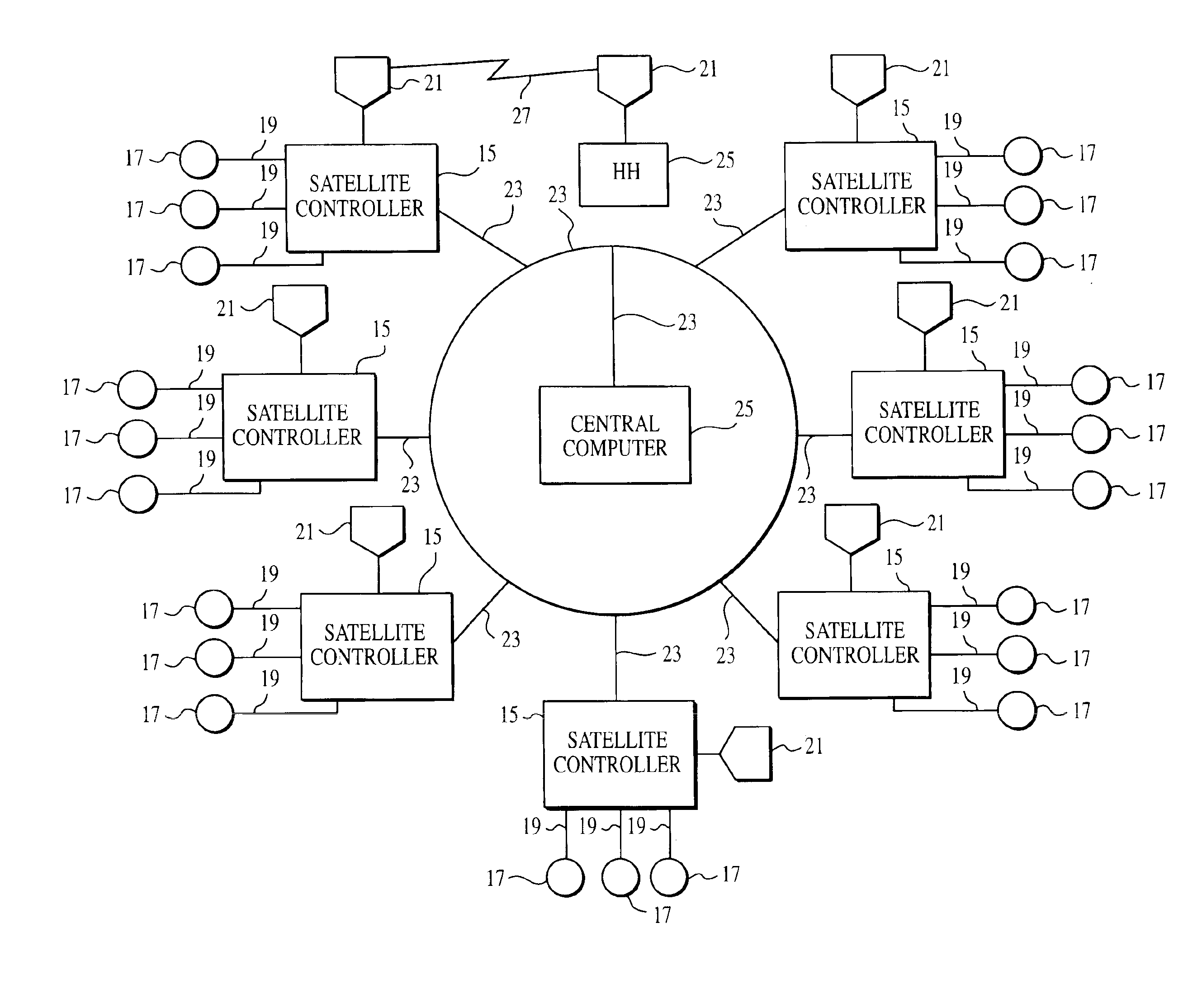
[0029]Reference is made to FIG. 3, which depicts the block diagram of the distributed control network for irrigation management. The control network is a peer-to-peer network wherein the entire system, or any portion thereof, can be monitored and operated from any node in the network. Several satellite controllers 15 are connected to one another, and further connected to a central computer 25, all via a communication bus 23. FIG. 3 is not meant to limit the number of satellite controllers 15 that can be connected to the communication bus 23. The satellite controllers 15 operate as nodes in the peer-to-peer network wherein the entire control system can be monitored and operated.

[0030]In the system depicted in FIG. 3, the satellite controllers 15 perform a variety of functions. The satellite controllers 15 control the solenoid operated valves 17 and interface with various sensors 21. Any standard solenoid is acceptable. Preferably, the satellite controller can operate up to 96 valves....


PUM


Abstract

A system and method for operating a distributed control network for irrigation management. The system incorporates several irrigation controllers wherein each of the controllers can transmit, receive and respond to commands initiated by any device or satellite controller on the network, a communication bus that is connected to the controllers, a central computer that is connected to the bus, several sensing devices that are connected to each controller, and several sprinkler valves that are connected to each controller. The controllers can be operated in local mode via a user interface and in a remote mode via a wireless connection. The controllers are capable of monitoring and acknowledging the commands that are transmitted on the bus.

Description

RELATED APPLICATION[0001]This application is a continuation of U.S. patent application Ser. No. 09 / 537,093, filed Mar. 29, 2000, now U.S. Pat. No. 6,600,971, which is incorporated herein by reference.BACKGROUND OF THE INVENTION[0002]1. Field of the Invention[0003]The present invention relates to an irrigation control system. More particularly, the invention relates to a peer-to-peer irrigation sprinkler control system with the ability to monitor and control the entire system from any satellite controller.[0004]2. Description of the Related Art[0005]In the area of irrigation management and control, there are two significant types of control systems that are used: the stand-alone controller and the central-satellite system. FIG. 1 shows a traditional stand-alone controller 1, which is typically used for smaller irrigation sites, with outputs varying from four (4) to approximately forty eight (48) outputs. The stand-alone controller 1 is a device that is usually wall mounted, and offer...

Claims


Application Information

Patent Timeline
Patent Type & Authority Patents(United States)
IPC IPC(8): G05B19/042G05B19/04G05B15/02
CPCG05B15/02G05B19/0421G05B2219/2229G05B2219/23043G05B2219/2625G05B2219/25192G05B2219/25232G05B2219/25428G05B2219/25187
Inventor SMITH, BRIAN J.SCHAFER, ERIC
Owner SIGNATURE CONTROL SYST
Why Eureka
Try Eureka