Control apparatus for internal combustion engine and control method for internal combustion engine combustion method for internal combustion engine and direct injection engine

a control apparatus and internal combustion engine technology, applied in the direction of electric control, machines/engines, output power, etc., can solve the problems of unstable combustion performance, a variety of egr gas to be introduced into the combustion chamber,

Inactive Publication Date: 2005-05-31
HITACHI LTD
View PDF13 Cites 11 Cited by
  • Summary
  • Abstract
  • Description
  • Claims
  • Application Information

AI Technical Summary

Benefits of technology

[0008]It is therefore an object of the present invention to provide a direct injection type gasoline engine that is capable of stabilized combustion regardless of whether a large amount of EGR gas is introduced into the combustion chamber.

Problems solved by technology

Because of this arrangement, the amount of EGR gas to be introduced into the combustion chamber is restricted in a variety of ways, being limited to a relatively small amount.
If the amount of EGR gas is made large, on the other hand, the distribution of rich-to-lean air-fuel mixture ratios in the combustion chamber exhibits no reproducibility, resulting in unstable combustion performance.

Method used


Image

  • Control apparatus for internal combustion engine and control method for internal combustion engine combustion method for internal combustion engine and direct injection engine
  • Control apparatus for internal combustion engine and control method for internal combustion engine combustion method for internal combustion engine and direct injection engine
  • Control apparatus for internal combustion engine and control method for internal combustion engine combustion method for internal combustion engine and direct injection engine

Examples


Embodiment Construction

[0039]Background of techniques relating to the present invention will be described in the following for reference.

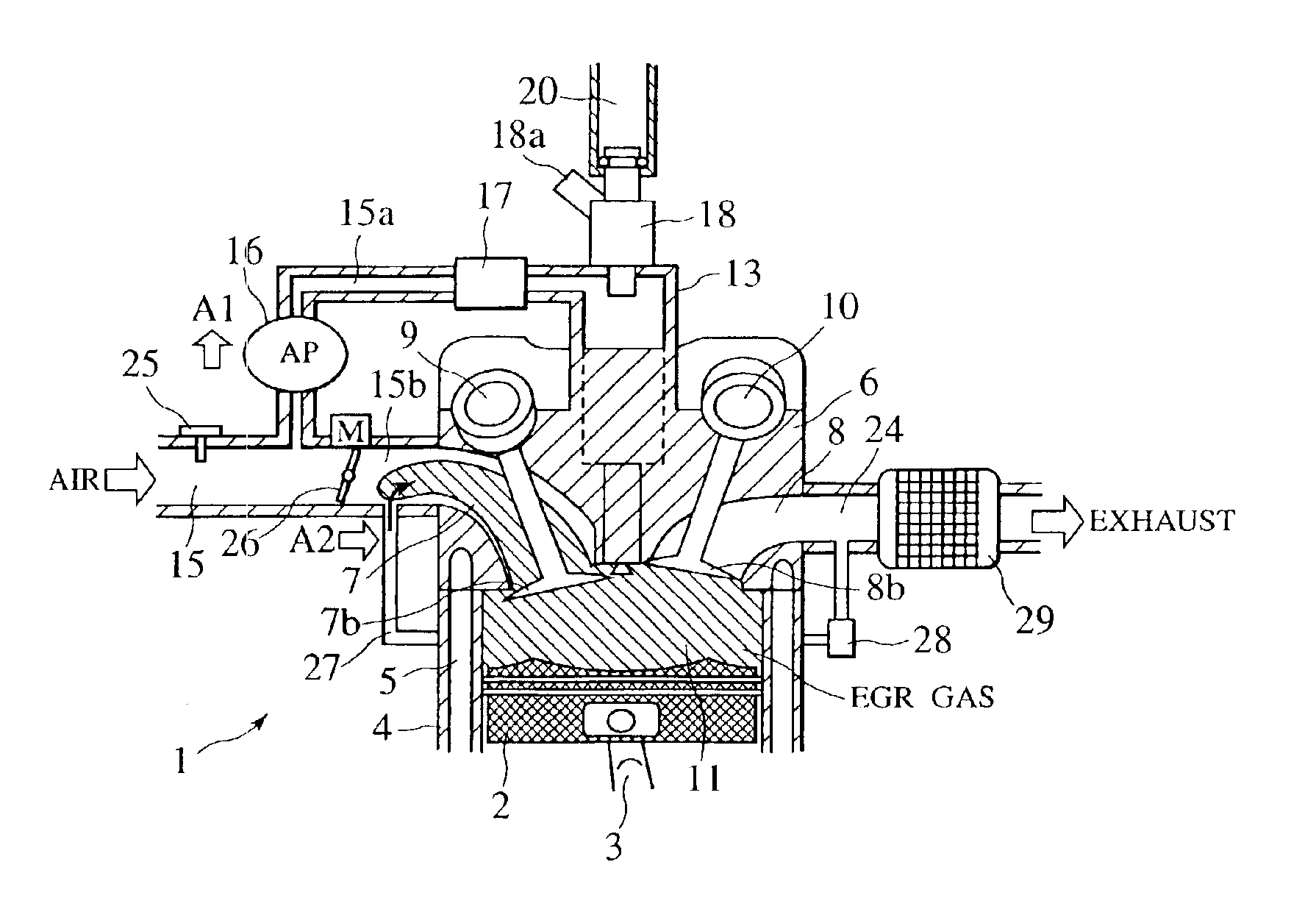
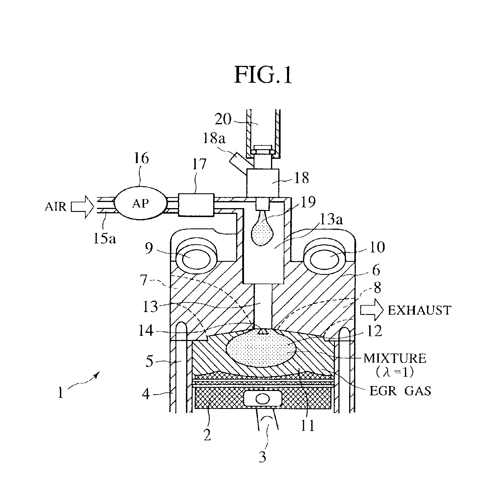
[0040]There is a growing need for automotive and other engines to reduce fuel consumption from standpoints of global environmental conservation and energy saving. As a technique to meet that need in the field of the gasoline engine, direct injection engines that have a fuel injection point inside a combustion chamber of the engine have been put into practical use. The direct injection configuration permits stratified charge combustion with an air-fuel ratio of 40 or more, thus reducing a pump loss for an even lower fuel consumption.

[0041]There is, however, a large amount of oxygen left in exhaust gases during stratified charge combustion. A conventional problem, in which three-way catalysts used for purification of exhaust emissions are not effective enough to purify NOx, has remained unsolved. To solve this problem, a lean NOx catalyst that is capable of reducing NOx ev...


PUM


Abstract

A gasoline engine is provided which is capable of introducing a large amount of EGR gas for performing homogeneous combustion and thus offering a good fuel economy. An external EGR mechanism or an internal EGR mechanism is used to introduce an EGR gas into a combustion chamber (a cylinder). A mixture of fresh air and fuel is thereafter directly injected from a mixture injection valve into the combustion chamber, thereby forming a region of said mixture in an area near an ignition plug. In addition, engine operating parameters are controlled in accordance with the amount of fresh air supplied into the combustion chamber (cylinder) after an intake valve has been closed. This makes possible homogeneous combustion using a large amount of EGR, which eventually increases fuel economy.

Description

BACKGROUND OF THE INVENTION[0001]The present invention relates to an internal combustion engine that directly injects gasoline into a combustion chamber (which is equivalent in meaning to a cylinder) for combustion, namely a direct injection type gasoline engine. More specifically, it relates to an improvement made on an internal combustion engine of this type involving homogeneous combustion.[0002]Japanese Patent Laid-open No. Hei 9-280138 discloses a direct injection type gasoline engine in which, in a technique as the prior art, a mixture of EGR gas and fuel (gasoline) is formed outside a combustion chamber and is then directly injected into the combustion chamber. A technique as an invention is also described in the publication, in which a mixture of compressed air and fuel (gasoline) is formed outside the combustion chamber and is directly supplied into the combustion chamber.[0003]Japanese Patent Laid-open No. 2000-97032 describes a direct injection type gasoline engine in whi...

Claims


Application Information

Patent Timeline
Patent Type & Authority Patents(United States)
IPC IPC(8): F02M61/00F02M61/16F02D41/14F02M61/08F02B47/00F02D13/02F02M67/12F02B17/00F02M67/00F02M67/02F02B47/08F02D11/10F02M25/07F02B13/06F02B1/12F02B13/08F02B23/10F02D21/08F02M23/04F02M61/14
CPCF02B47/08F02D11/105F02D13/0246F02D13/0249F02D13/0261F02D13/0265F02D41/1497F02M25/0742F02M25/0752F02M61/08F02M61/162F02M67/02F02M67/12F02B17/005F02B1/12Y02T10/18F02D2041/3088F02D2041/389F02D2250/18F02M2025/0769F02M26/01F02M26/36F02M2026/009Y02T10/12
Inventor SHIRAISHI, TAKUYANOGI, TOSHIHARU
Owner HITACHI LTD
Why Eureka
Try Eureka