
Starter unit and method for matching starter units in drive systems to different limiting conditions, in particular different drive engines

a technology of starter units and drive systems, applied in the direction of fluid gearings, gearing control, couplings, etc., can solve the problems of large assembly effort, low design efficiency, and relatively short build time of the solution, and achieve the effect of satisfying the requirements of certain prescribed installation requirements, reducing the number of design components, and reducing the number of assembly steps

Inactive Publication Date: 2005-05-31
VOITH TURBO GMBH & CO KG
View PDF25 Cites 3 Cited by
  • Summary
  • Abstract
  • Description
  • Claims
  • Application Information

AI Technical Summary

Benefits of technology

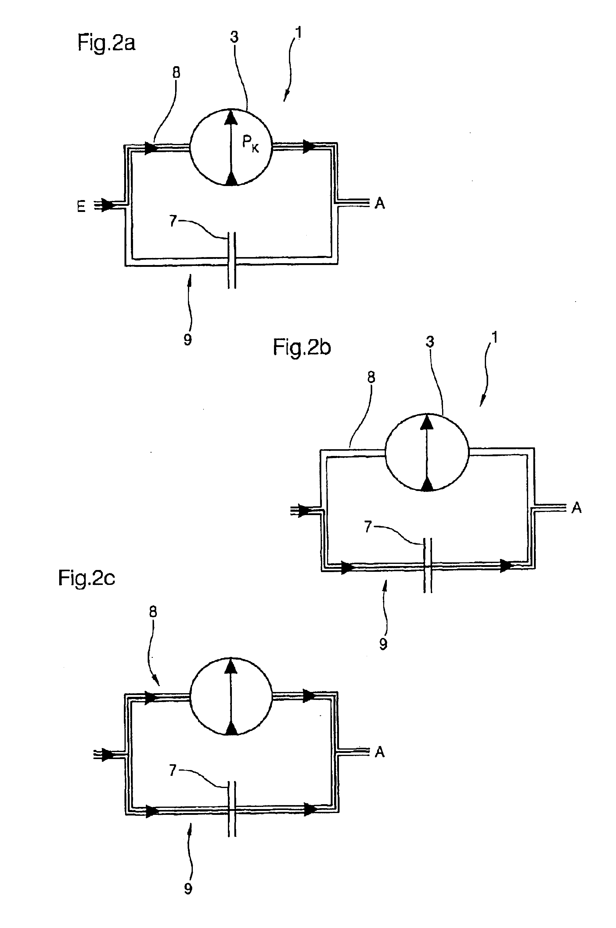
[0006]The solution described in the invention makes it possible, if necessary, to divide the transferable power into two power branches and bring them back together at the output. The possible transfer either via only one branch or via both branches offers the advantage that the starter unit can be achieved with the individual design elements without changing the layout in different drive systems for use and will be optimally adaptable to the limiting conditions of the type of use in question. Because according to a particularly advantageous further development, the individual power portions are free, i.e. may be controlled independent of each other, there is also the possibility of creating different starting characteristics.
[0044]Preferably the latter possibility will be used because, in this case, the collision possibilities of the individual elements can be optimally controlled despite a small design space.

Problems solved by technology

This solution has relatively short build but does not, however, fulfill the requirements of certain prescribed installation situations with respect to the required axial design length.
Furthermore, this execution is characterized by a high number of design components and enormous assembly effort due to the high number of functional elements.

Method used


Image

  • Starter unit and method for matching starter units in drive systems to different limiting conditions, in particular different drive engines
  • Starter unit and method for matching starter units in drive systems to different limiting conditions, in particular different drive engines
  • Starter unit and method for matching starter units in drive systems to different limiting conditions, in particular different drive engines

Examples


Embodiment Construction

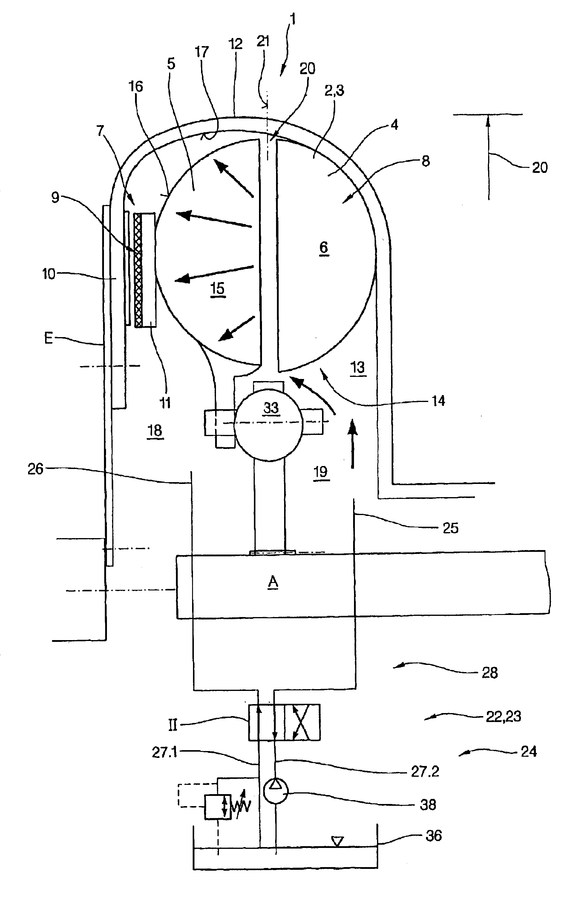
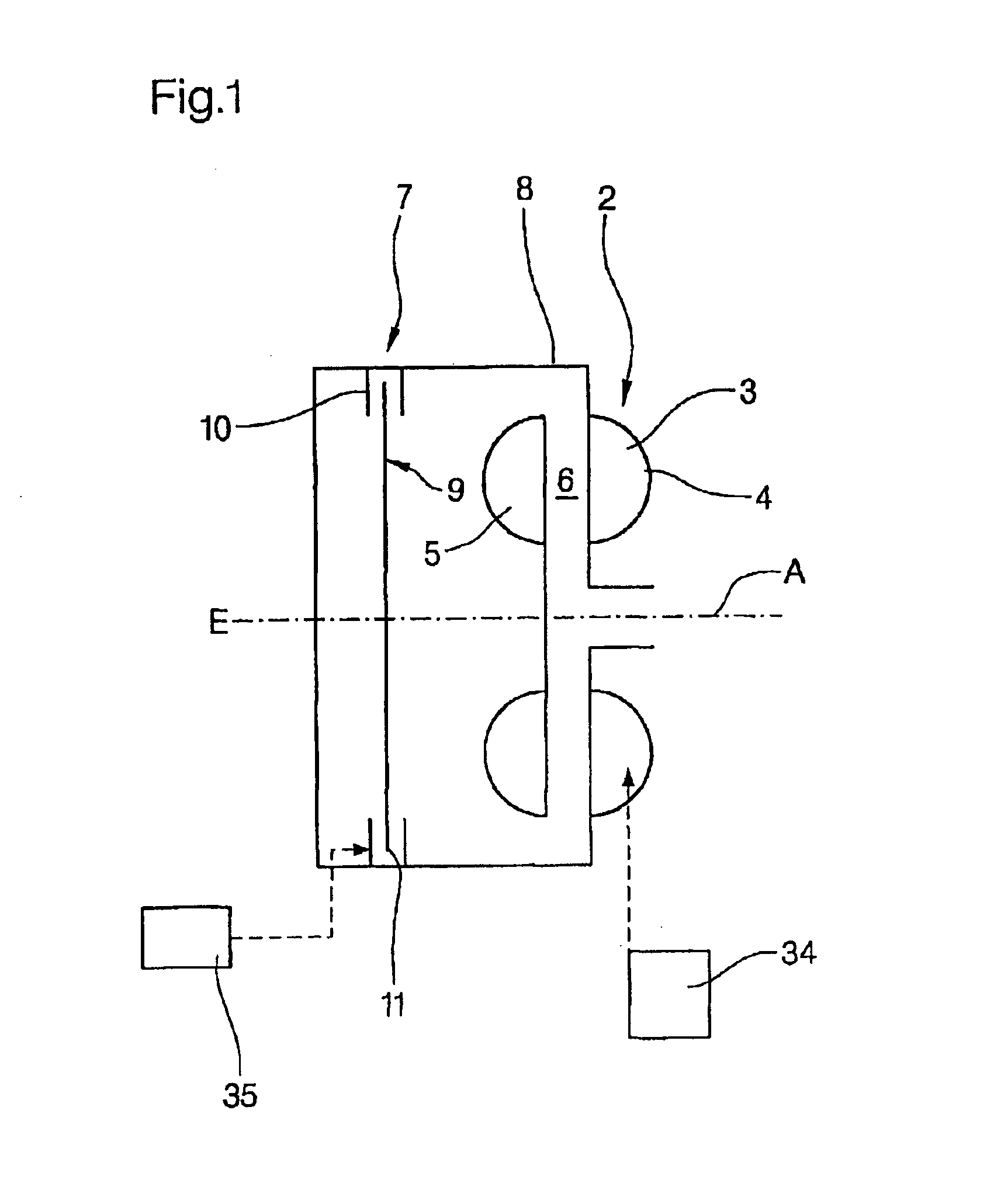
[0058]FIG. 1 illustrates in a schematically simplified display the basic construction of a starter unit 1 formed according to the invention. The starter unit 1 encompasses an input E that may be coupled with a drive and an output A that may be coupled with open gear transfer steps or a drive. The starter unit 1 encompasses a starter element 2 in the form of the hydrodynamic coupling 3. The hydrodynamic coupling 3 encompasses two blade wheels, one primary wheel functioning as a pump wheel 4 and a secondary wheel functioning as a turbine wheel 5, which together form a working chamber 6 which normally has a toroidal shape. The starter unit 1 also encompasses a clutch 7 that may be switched parallel to the starter element in the form of hydrodynamic coupling 3. According to the invention, the hydrodynamic coupling 3 and the switchable clutch may be switched separately or jointly. The hydrodynamic coupling 3 and the switchable clutch are thereby arranged in two different power branches, ...


PUM


Abstract

The invention relates to a starter unit (1) comprising an input (E) which may be coupled to a drive input, an output (A) which may he coupled to a drive output, a starter element (2) in the form of a hydrodynamic coupling (3), a switchable clutch (7), comprising at least two clutch elements, which may be brought into frictional engagement, either directly or indirectly, by means of further transfer agents, being a first clutch element (10) and a second clutch element (11) each rotationally fixed to the input (E) and the output (A) respectively. The hydrodynamic coupling (3) and the switchable clutch (7) are arranged in a parallel fashion in two power branches (8,9) and may be activated individually or in common.

Description

BACKGROUND OF THE INVENTION[0001]The invention relates to a starter unit, and a method for matching starter units in drive systems to different limiting conditions, in particular different drive engines.[0002]Starter units for use in manual transmissions, automatic transmissions and automated gears are known. As a rule, these encompass a hydrodynamic design element in the form of a hydrodynamic revolution / torque converter or a hydrodynamic coupling. DE 198 04 635 A1 relates to a feasible execution of a starter unit for use in gears with a hydrodynamic coupling. This document discloses an execution of a starter unit with a short axial design length, encompassing a pump wheel and a turbine wheel that together form a toroidal working chamber, whereby the pump wheel is arranged on the motor drive side, i.e. the turbine wheel is spatially arranged between the input of the starter unit and the pump wheel. For this purpose, the pump wheel is connected in a rotationally fixed manner with th...

Claims


Application Information

Patent Timeline
Patent Type & Authority Patents(United States)
IPC IPC(8): F16H45/00F16D33/18F16D33/06F16D33/16F16H61/14F16H45/02F16D33/00F16H41/24
CPCF16D33/06F16D33/16F16H61/14F16D33/18F16H2312/02F16H2045/0215
Inventor HOLLER, HEINZKERNCHEN, REINHARDMENNE, ACHIMKLEMENT, WERNER
Owner VOITH TURBO GMBH & CO KG
Learn More