Organ manipulator having suction member supported with freedom to move relative to its support

a technology of suction member and manipulator, which is applied in the field of organ manipulator, can solve the problems of insufficient space, heart failure, and difficulty in accessing cxa, rca and pda, and achieve the effects of reducing the amount of compressive deformation of the heart, facilitating oxygenation during surgery, and not compromising hemodynamic function

Inactive Publication Date: 2005-05-31
MAQUET CARDIOVASCULAR LLC
View PDF110 Cites 55 Cited by
  • Summary
  • Abstract
  • Description
  • Claims
  • Application Information

AI Technical Summary

Benefits of technology

[0021]In a class of embodiments, the invention is an organ manipulator including at least one suction member (e.g., a suction cup) and preferably also a compliant joint to which the suction member is mounted. The compliant joint provides built-in system compliance so that when the suction member supports an organ (e.g., a beating heart) by suction, the suction member does not constrain normal motion of the organ (e.g., normal beating motion of the heart), either during gross movement of the organ into a retracted position or during surgery with the organ attached to or held by the suction member in the retracted position. In preferred embodiments the suction member is shaped and configured to retract a beating heart and suspend it in the retracted position during surgery. As the suspended heart beats, the compliant joint allows the heart to expand and contract freely (and otherwise move naturally) so that hemodynamic function is not compromised. Suspension of the beating heart below the suction member tends to expand the heart chambers, which in turn tends to reduce the amount of compressive deformation of the heart and great vessels which would otherwise result from pressing the heart with a stabilization device (such as stabilization feet) during surgery, so that the invention assists in oxygenation during surgery.
[0024]In preferred embodiments, the compliant joint couples the suction member to an arm (which is rigid or can be placed in a rigid state), and the arm is adjustably mounted to a fixed mounting structure. The mounting structure can be a conventional sternal retractor (of the type used to maintain a sternal incision in an open state for cardiac access), an operating table, or another rigid structure. When the organ is attached to or held by (e.g., suspended below) the suction member, the compliant joint gives the suction member freedom to move (at least axially along the axis of the suction member, e.g., vertically when the suction member has a vertical axis) relative to the arm and mounting structure in response to normal organ movement (e.g., beating of a heart) to avoid compromising the normal functioning of the organ. When a beating heart is suspended below the suction member, the compliant joint allows the heart to expand and contract freely (at least vertically) as it beats. Optionally, the compliant joint also gives the organ freedom to rotate about the axis of the suction member (typically, a vertical axis) and / or to swing relative to the arm.
[0025]In preferred embodiments, the inventive apparatus provides for compliant retraction of a beating heart (or other organ) in the sense that it retracts the organ via suction, while allowing normal myocardial movement (or other normal organ movement) in at least the vertical direction, and optionally also allowing normal organ movement perpendicular to the vertical direction (e.g., pivoting or twisting motion about a vertical axis). In some such preferred embodiments, the compliant joint is a sliding ball joint attached to a movable arm, and the arm can be locked in any of a variety of positions (relative to a fixed supporting structure) to allow adjustable degrees of organ retraction. The compliance provided by the ball joint allows the organ to better tolerate manipulation.
[0026]Preferably, the suction member is specially designed to decrease trauma to the heart muscle (or other organ tissue) during attachment, and the apparatus is preferably implemented to have one or more of the following features: an absorbent cup lining for increased holding power, a smooth and soft inner cup surface to decrease myocardial bruising (hematoma formation) and to diffuse the suction across the cup, a means for regulation of suction intensity, and a vacuum accumulator in the suction line to decrease immediate loss of holding power with variations in vacuum supply.
[0028]In other embodiments, the invention is a method for compliant retraction of an organ, including the steps of retracting the organ using suction, and supporting the organ in the retracted position using suction, in such a manner that the organ has freedom to move normally (e.g., to beat or undergo other limited-amplitude motion) at least in the direction in which the suction is exerted during both steps. In some such embodiments, the method includes the steps of retracting the organ using suction, and suspending the organ in the retracted position using suction, in such a manner that the organ has freedom to move normally (e.g., to beat or undergo other limited-amplitude motion) in at least the vertical direction during both steps. One embodiment is a method for retracting a beating heart, including the steps of affixing a suction member (e.g., a suction cup) to the heart at a position concentric with the apex of the heart (preferably the suction member has sufficient curvature to conform with the apex and is shaped to be at least generally symmetric with the apex) and applying suction to the heart (e.g., by coupling the suction member to a vacuum source), and moving the suction member to retract the heart to a desired position for surgery such that the heart has freedom to undergo normal beating motion (at least along the axis of the suction member) during retraction. Preferably, the suction member is mounted to a fixed assembly (e.g., a fixedly mounted sternal retractor) by a compliant joint in such a manner that the suction member does not constrain normal beating motion of the heart, either during gross movement of the member (with heart) into the desired position or while the heart is supported by (e.g., suspended vertically below) the member during surgery in such position. In such preferred embodiments, as the heart beats, it is free to expand and contract normally (with the compliant joint allowing the suction member to oscillate along the axis of the suction member, and optionally also to twist about such axis) so that hemodynamic function is not compromised.

Problems solved by technology

It is very difficult to access the CxA, RCA, and PDA without a sternotomy, as the heart needs to be turned or tilted (or turned and tilted) significantly to reach its side or back, and with an intact sternum, insufficient space exists for these maneuvers.
An additional challenge to beating heart surgery is that some hearts do not tolerate manipulation well from a hemodynamic standpoint.
However, conventional use of pericardial sutures for retraction of a beating heart has limitations and disadvantages including the following.
It is inconvenient and potentially harmful to the patient to incise the pericardium and insert sutures along cut edges of the pericardium, and then exert tension on the sutures to move the heart together as a unit with the pericardium.
However, such tissue stabilization products cannot duplicate the function of the inventive apparatus.
Devices designed specifically for tissue stabilization are not well suited to those motions.
However, no conventional Octopus device can support a beating heart with adequate compliance to allow normal heart beating movement, and instead each conventional Octopus device would exert compressive or twisting force on at least one side of the beating heart, thereby constraining cardiac contraction and expansion.
Also, one of the small-diameter suction cups of a conventional Octopus device would be too small to reliably grip (and support) the heart without causing trauma to the heart surface.
Thus, in order to reliably (but atraumatically) retract and support the heart in the retracted position, many small-diameter suction cups (supported on a rigid frame which frame is itself rigidly supported) need to exert suction simultaneously on the heart, which exacerbates the problem of constrained cardiac contraction and expansion due to the exertion of compressive or twisting force on the heart.
The inventive apparatus is not designed to stabilize specific areas of the organ.
A disadvantage of the bumps is that they would likely cause trauma to the organ being manipulated (even with a vacuum in the preferred range).
U.S. Pat. No. 5,799,661 does not teach attaching the suction cup to the shaft by a joint which provides limited freedom to translate along a first axis and / or full (or at least limited) freedom to rotate about the first axis, but no significant freedom to translate in directions perpendicular to the first axis.
Although the device is said to allow the heart to beat in a “relatively normal” manner during surgery, the device is rigidly mounted to a fixed mounting structure during surgery, and thus neither the device nor the part of the heart surface which it immobilizes would have freedom to move significantly relative to the mounting structure during surgery.

Method used


Image

  • Organ manipulator having suction member supported with freedom to move relative to its support
  • Organ manipulator having suction member supported with freedom to move relative to its support
  • Organ manipulator having suction member supported with freedom to move relative to its support

Examples


Embodiment Construction

[0069]Throughout this disclosure, including in the claims, the expression “compliant joint” is used in a broad sense to denote any mechanical coupling capable of bearing the load of the inventive suction member (and the organ attached by suction to the suction member) while allowing the suction member (and organ) freedom to move in the described manner. The compliant joint can be implemented in any of a wide variety of ways, including (but not limited to) a sliding ball joint, a hinged joint, a pin which slides in a slot, a universal joint, or a spring assembly in which the spring constant is determined by a bellows, piston, metal spring, or some other compliant element).

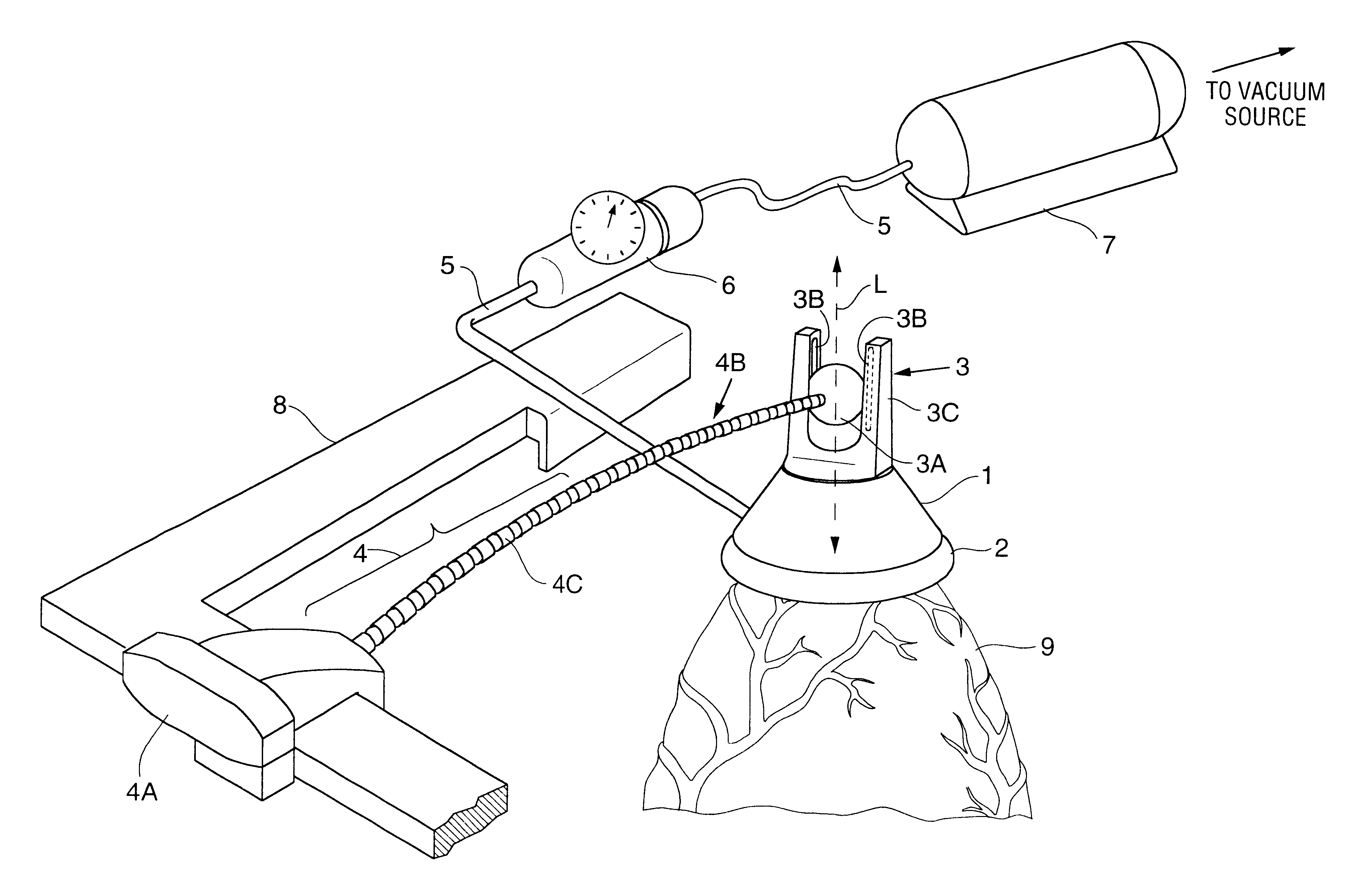
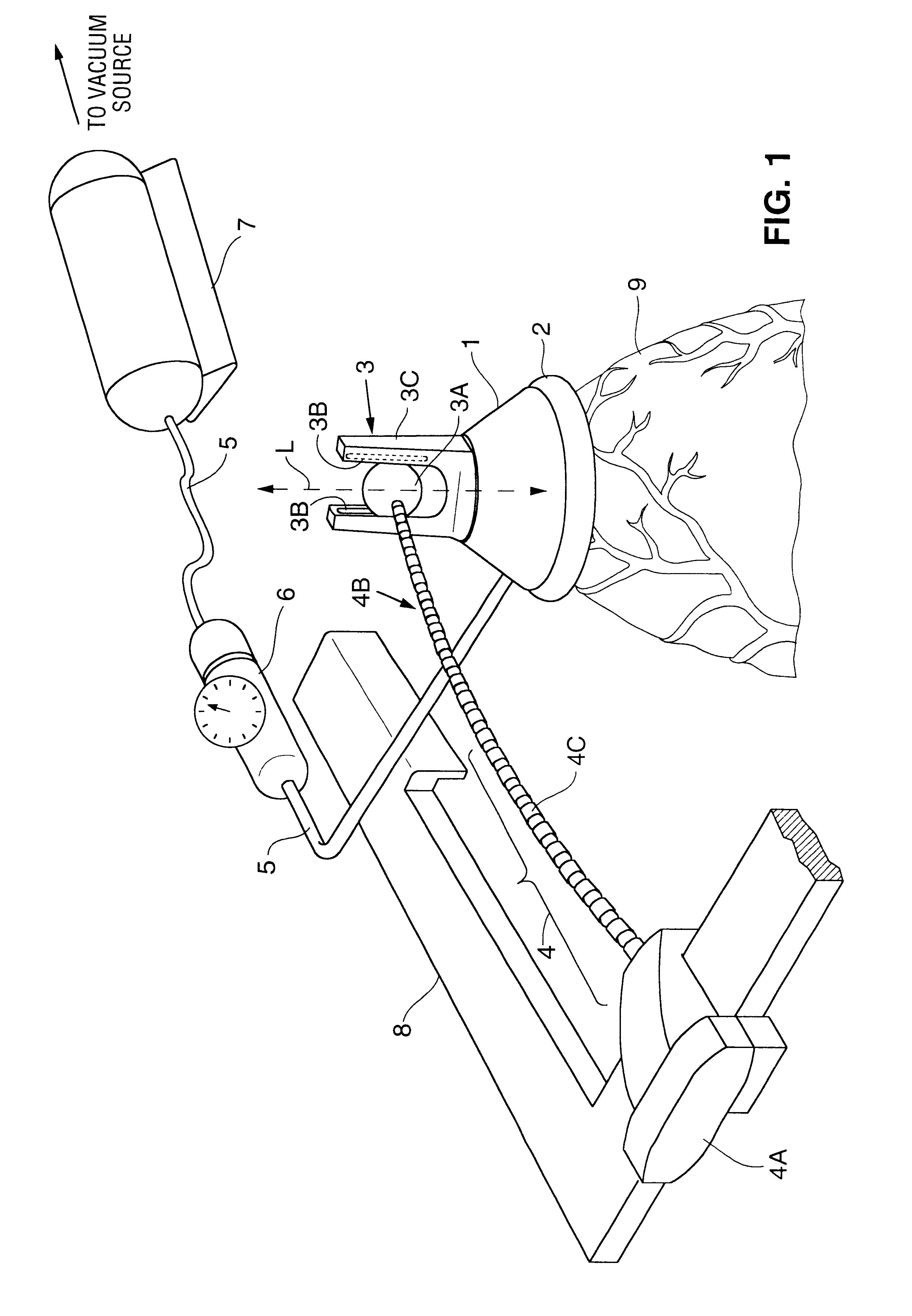
[0070]A first preferred embodiment of the invention will be described with reference to FIG. 1.

[0071]The FIG. 1 embodiment is designed to retract heart 9 (by exerting suction) to a position suitable for performing surgery thereon, and to retain heart 9 in the retracted position (by continued exertion of suction ther...


PUM


Abstract

An organ manipulator including at least one suction member or adhesive disc mounted to a compliant joint, a flexible locking arm for mounting such suction member or compliant joint, and a method for retracting and suspending an organ in a retracted position using suction (or adhesive force) so that the organ is free to move normally (e.g., to beat or undergo other limited-amplitude motion) in at least the vertical direction during both steps. In preferred embodiments, a suction member exerts suction to retract a beating heart and suspend it in a retracted position during surgery. As the retracted heart beats, the compliant joint allows it to expand and contract freely (and otherwise move naturally) at least in the vertical direction so that hemodynamic function is not compromised. The suction member conforms or can be conformed to the organ anatomy, and its inner surface is preferably smooth and lined with absorbent material to improve traction without causing trauma to the organ. The compliant joint can connect the member to an arm which is adjustably mounted to a sternal retractor or operating table. The compliant joint can be a sliding ball joint, a hinged joint, a pin sliding in a slot, a universal joint, a spring assembly, or another compliant element. In preferred embodiments, the method includes the steps of affixing a suction member to a beating heart at a position concentric with the heart's apex, and applying suction to the heart while moving the member to retract the heart such that the heart has freedom to undergo normal beating motion at least in the vertical direction during retraction.

Description

[0001]This application is a continuation of application Ser. No. 09 / 390,792, filed Sep. 7, 1999, now U.S. Pat. No. 6,506,149, which is incorporated herein by reference in its entirety and to which application we claim priority under 35 USC §120.FIELD OF THE INVENTION[0002]The invention pertains to an apparatus for manipulating (and supporting in a retracted position) an organ such as a beating heart. Preferred embodiments of the invention pertain to an apparatus for support and manipulation of a beating heart during surgery thereon, in a manner promoting oxygenation during the surgery.BACKGROUND OF THE INVENTION[0003]Coronary artery bypass grafting (CABG) has traditionally been performed with the use of a cardiopulmonary bypass (CPB) machine to oxgenate and perfuse the body during surgery. Recently, techniques have been developed to allow for performing CABG without the use of CPB by stabilizing the epicardial surface of a beating heart at the coronary anastomotic site with a stabil...

Claims


Application Information

Patent Timeline
Patent Type & Authority Patents(United States)
IPC IPC(8): A61B17/02A61B17/28A61B17/30A61B17/03A61B17/08A61B19/00
CPCA61B17/02A61B17/085A61B2017/0243A61B2017/308A61B2017/2929A61B2017/293A61B2017/2905
Inventor PENG, STEVENVOSS, LARRYHANCOCK, DAVID E.CARLSON, GRACE A.DAVIS, JOHNCHIN, ALBERT K.VARGAS, JAIME S.
Owner MAQUET CARDIOVASCULAR LLC
Why Eureka
Try Eureka