Method of respiratory gas analysis using a metabolic calorimeter

a metabolic calorimeter and gas analysis technology, applied in the field of respiratory instruments, can solve the problems of high cost, high accuracy of capnometer used with instruments to measure carbon dioxide concentration, and substantially higher error in the resulting determination of oxygen conten

Inactive Publication Date: 2005-05-31
MICROLIFE MEDICAL HOME SOLUTIONS
View PDF22 Cites 224 Cited by
  • Summary
  • Abstract
  • Description
  • Claims
  • Application Information

AI Technical Summary

Problems solved by technology

The scrubber used with certain of these systems was relatively bulky and required replenishment after extended usage.
The capnometers used with the instruments to measure carbon dioxide concentration had to be highly precise and accordingly expensive because any error in measurement of the carbon dioxide content of the exhalation produces a substantially higher error in the resulting determination of the oxygen content of the exhalation.

Method used


Image

  • Method of respiratory gas analysis using a metabolic calorimeter
  • Method of respiratory gas analysis using a metabolic calorimeter
  • Method of respiratory gas analysis using a metabolic calorimeter

Examples


Embodiment Construction

Basic Configuration of Calorimeter

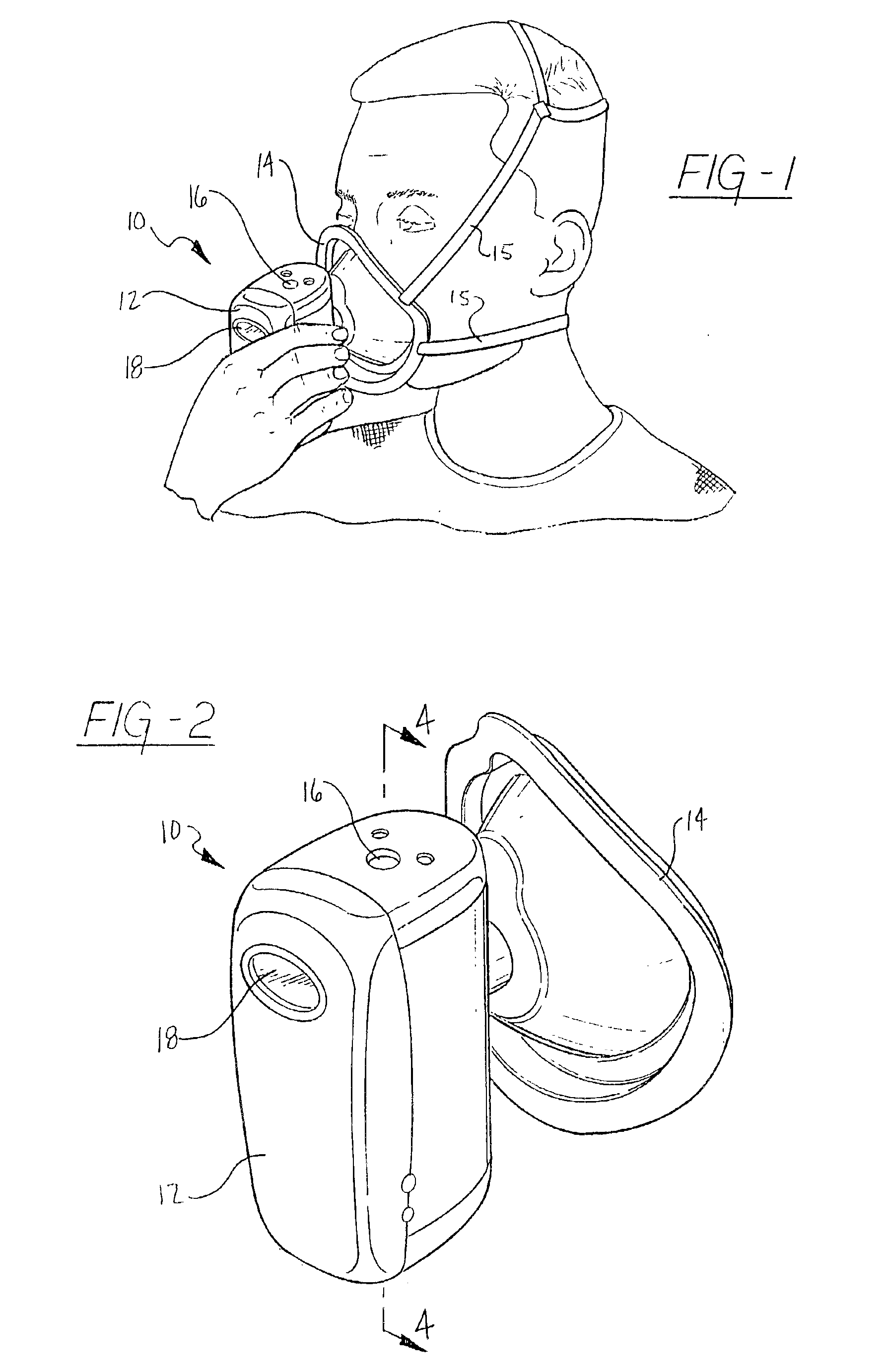
[0039]Referring to FIGS. 1 and 2, a respiratory calorimeter according to the present invention is generally shown at 10. The calorimeter 10 includes a body 12 and a respiratory connector, such as mask 14, extending from the body 12. In use, the body 12 is grasped in the hand of a user and the mask 14 is brought into contact with the user's face so as to surround their mouth and nose, as best shown in FIG. 1. An optional pair of straps 15 is also shown in FIG. 1. The straps provide an alternative to holding the body 12 of the calorimeter 10 with a hand. Instead, the straps can support the mask and calorimeter in contact with the user's face.

[0040]With the mask 14 in contact with their face, the user breathes normally through the calorimeter 10 for a period of time. The calorimeter 10 measures a variety of factors and calculates one or more respiratory parameters, such as oxygen consumption and metabolic rate. A power button 16 is located on the top s...


PUM

PropertyMeasurementUnit
widthaaaaaaaaaa
heightaaaaaaaaaa
internal diameteraaaaaaaaaa

Abstract

A method of determining a respiratory parameter for a subject using an indirect calorimeter is provided. The indirect calorimeter includes a respiratory connector for passing inhaled and exhaled gases, a flow pathway operable to receive and pass inhaled and exhaled gases having a flow tube within the flow pathway through which the inhaled and exhaled gases pass, a flow meter for determining an instantaneous flow volume of the inhaled and exhaled gases, a component gas concentration sensor for determining an instantaneous fraction of a predetermined component gas and a computation unit having a processor and a memory. The method includes the steps of initializing the indirect calorimeter and the subject breathing into the respiratory connector if the indirect calorimeter is initialized, sensing the flow volume of the inhaled and exhaled gases passing through the flow pathway using the flow meter and transmitting a signal representing the sensed flow volume to the computation unit. The method also includes the steps of sensing a concentration of a predetermined component gas as the inhaled and exhaled gases pass through the flow pathway using the component gas sensor, and transmitting a signal representing the sensed concentration of the predetermined component gas to the computation unit. The method further includes the steps of calculating at least one respiratory parameter for the subject as the subject breathes through the calorimeter using the sensed flow volume and the sensed concentration of the predetermined component gas, and providing the subject with the at least one respiratory parameter.

Description

REFERENCE TO RELATED APPLICATIONS[0001]This application is a continuation of U.S. application Ser. No. 09 / 630,398, now U.S. Pat. No. 6,468,222 filed Aug. 2, 2000, which claims priority from U.S. provisional patent applications Ser. Nos. 60 / 146,898, filed Aug. 2, 1999; 60 / 155,035, filed Sep. 20, 1999; 60 / 219,241, filed Jul. 18, 2000; and 60 / 218,863, filed Jul. 18, 2000, the entire contents of all are incorporated herein by reference.FIELD OF THE INVENTION[0002]This invention relates to a respiratory instrument for measuring metabolism and related respiratory parameters by indirect calorimetry and in particular to a method of respiratory gas analysis using a metabolic calorimeter.BACKGROUND OF THE INVENTION[0003]U.S. Pat. Nos. 4,917,108; 5,038,792; 5,178,155; 5,179,958; 5,836,300; and 6,309,360, all to Mault, a coinventor of the present application, are incorporated herein by reference. These patents disclose systems for measuring metabolism and related respiratory parameters through ...

Claims


Application Information

Patent Timeline
Patent Type & Authority Patents(United States)
IPC IPC(8): A61B5/091A61B5/087A61B5/08A61B5/083A61B5/22A61B5/11G01N33/483G01N33/497A61B5/024A61B5/00
CPCA61B5/0833G01N33/497A61B5/091A61B5/222A61B5/087A61B5/0002A61B5/02438
Inventor MAULT, JAMES R.PEARCE, JR., EDWIN M.BARBER, THEODORE W.LAWRENCE, CRAIG M.PRACHAR, TIMOTHY J.WEINTRAUB, JEFFREY C.NASON, KEVIN S.
Owner MICROLIFE MEDICAL HOME SOLUTIONS
Why Eureka
Try Eureka