Thermoplastic molding process and apparatus

a thermoplastic molding and thermoset technology, applied in the direction of turning machine accessories, drawing profiling tools, butter production, etc., can solve the problems of affecting the performance of parts, the inability to re-mold thermoset parts, and the weakness of concrete made with only sand and cement, etc., to facilitate the formation of thermoplastic composite structures and low fiber fracture rates

Inactive Publication Date: 2005-05-31
D&D MFG LLC
View PDF18 Cites 88 Cited by
  • Summary
  • Abstract
  • Description
  • Claims
  • Application Information

AI Technical Summary

Benefits of technology

[0029]“This extrusion-molding” process also facilitates the formation of thermoplastic composite structures reinforced with long fibers (greater than about one-half inch) because the extruder dispenses the molten, thermoplastic composite material through the dynamic die, gravitating the material directly onto a lower mold that is movable with respect to the position of the dynamic die. As used herein, the term “lower mold” refers to the lower half of a matched-mold into which thermoplastic material is directed. Similarly, the term “upper mold” refers to the upper half of the matched-mold within which the desired thermoplastic part is formed, when the upper and lower mold halves are combined i.e., closed. The lower mold may be moved via a trolley to fill the cavity of the mold with varying quantities of the thermoplastic composite material. For example, if the cavity defined by the lower and an upper mold is larger over a certain horizontal range, the lower mold may be slowed down to receive more molten thermoplastic composite material in that region. The dynamic die employs flow control elements that vary or regulate the flow of the molten extruded thermoplastic composite material to deliver different quantities of material from each of the flow control element, to deposit the material selectively across the width of the lower mold in a direction perpendicular to the direction it is moving. The thermoplastic composite material may be molded with long fibers (greater than about one-half inch) having a concentration of at least ten percent (10%) by weight to as much as fifty to sixty percent (50-60%) by weight, with low fiber-fracture rates. After the molten extruded thermoplastic composite material gravitates onto the lower mold, the trolley is automatically transported into a press that closes the upper mold onto the lower mold to form the composite part.

Problems solved by technology

Concrete made with only sand and cement is not nearly as strong as concrete made from cement, sand, and stones, which, in turn, is not as strong as concrete reinforced with steel, sand and stones.
Once cured, a thermoset part cannot be remolded.
The fatigue life refers to the period of time that a part lasts prior to exhibiting material wear or significant stress, to the point of impairing the ability of the part to perform to specification.
There are a number of parts made from thermoset composite materials that are quite expensive.
Since these methods are designed for resin systems with much lower viscosities and longer cure times, certain inefficiencies and difficulties have plagued the thermoplastic manufacturing process.
Compression molding does require a high capital investment, however, to purchase high capacity presses (2000-3000 tons of pressure) and high pressure molds, therefore it is only efficient for large production volumes.
Other disadvantages of the process are low fiber fractions (20% to 30%) due to viscosity problems, and the ability to only obtain intermediate quality surface finishes.
The process discussed above suffers from real limitations with respect to the size and weight of parts that can be produced by injection molding, because of the size of the required molds and capacity of injection molding machines.
Most problematic from a structural reinforcing point is the limitation regarding the length of reinforcement fiber that can be used in the injection molding process.
Because the autoclave process is much slower and more labor intensive, it is utilized primarily for very large, low volume parts that require a high degree of accuracy; it is not conducive for production lines.
None of the processes described above are capable of producing a thermoplastic composite reinforced with long fibers (i.e., greater than about one-half inch) that remain largely unbroken during the molding process itself, this is especially true for the production of large and more complex parts.
This process has several disadvantages that limit the industry's versatility for producing more complex, large parts with sufficient structural reinforcement.
One disadvantage is that the sheet-molding process cannot produce a part of varying thickness, or parts requiring “deep draw” of thermoplastic composite material.
The thicker the extruded sheet, the more difficult it is to re-melt the sheet uniformly through its thickness to avoid problems associated with the structural formation of the final part.
For example, a pallet having feet extruding perpendicularly from the top surface is a deep draw portion of the pallet that cannot be molded using a thicker extruded sheet because the formation of the pallet feet requires a deep draw of material in the “vertical plane” and, as such, will not be uniform over the horizontal plane of the extruded sheet.

Method used


Image

  • Thermoplastic molding process and apparatus
  • Thermoplastic molding process and apparatus
  • Thermoplastic molding process and apparatus

Examples


Embodiment Construction

[0051]For many years, a gap has existed in the composites manufacturing industry that failed to provide a process to mass produce large thermoplastic composite structures or parts at the rates and labor efficiencies of compression or injection molding, with the accuracy and low pressures of autoclave molding. The principles of the present invention provide for processes that closes this gap and produces such thermoplastic composite parts. The processes are suitable for mid to high production volumes of parts, and may produce large parts and structures with high reinforcing fiber concentration and at low molding pressures.

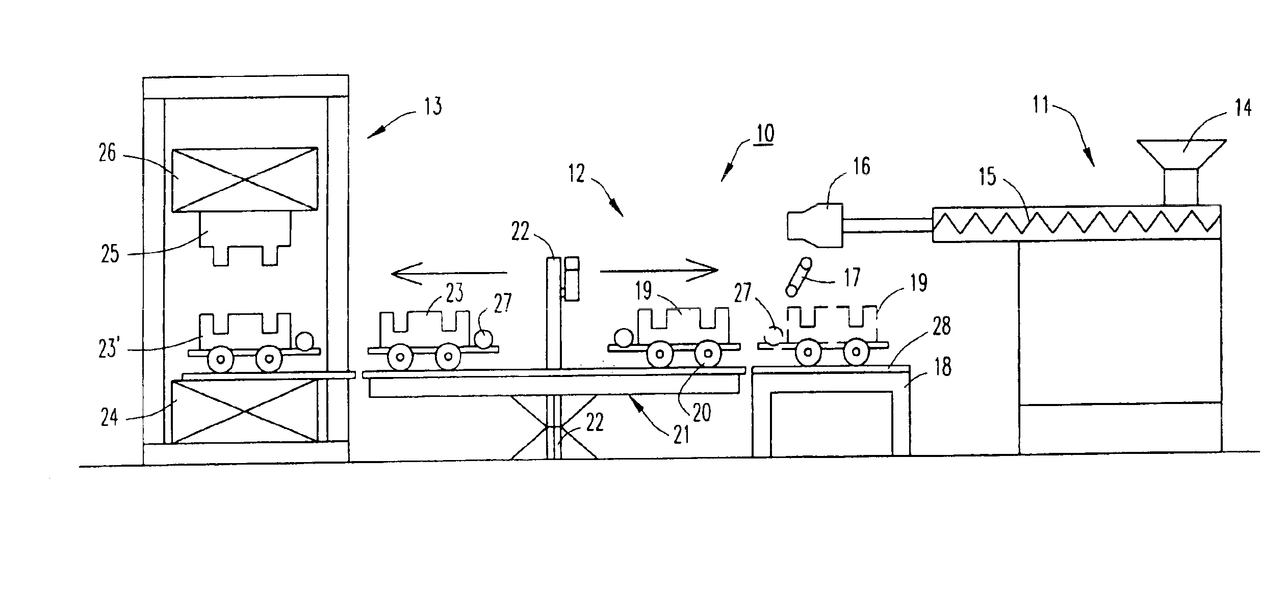
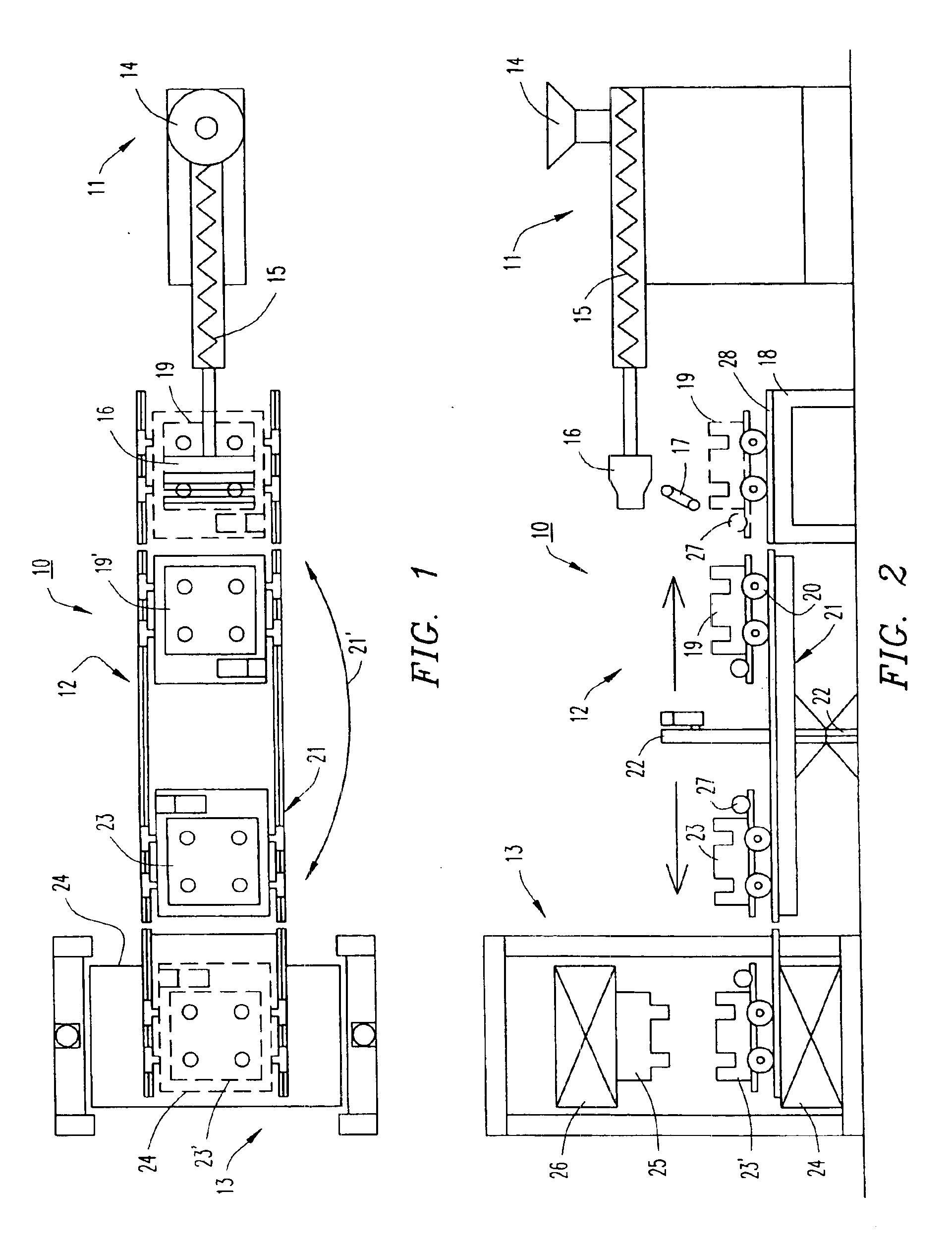
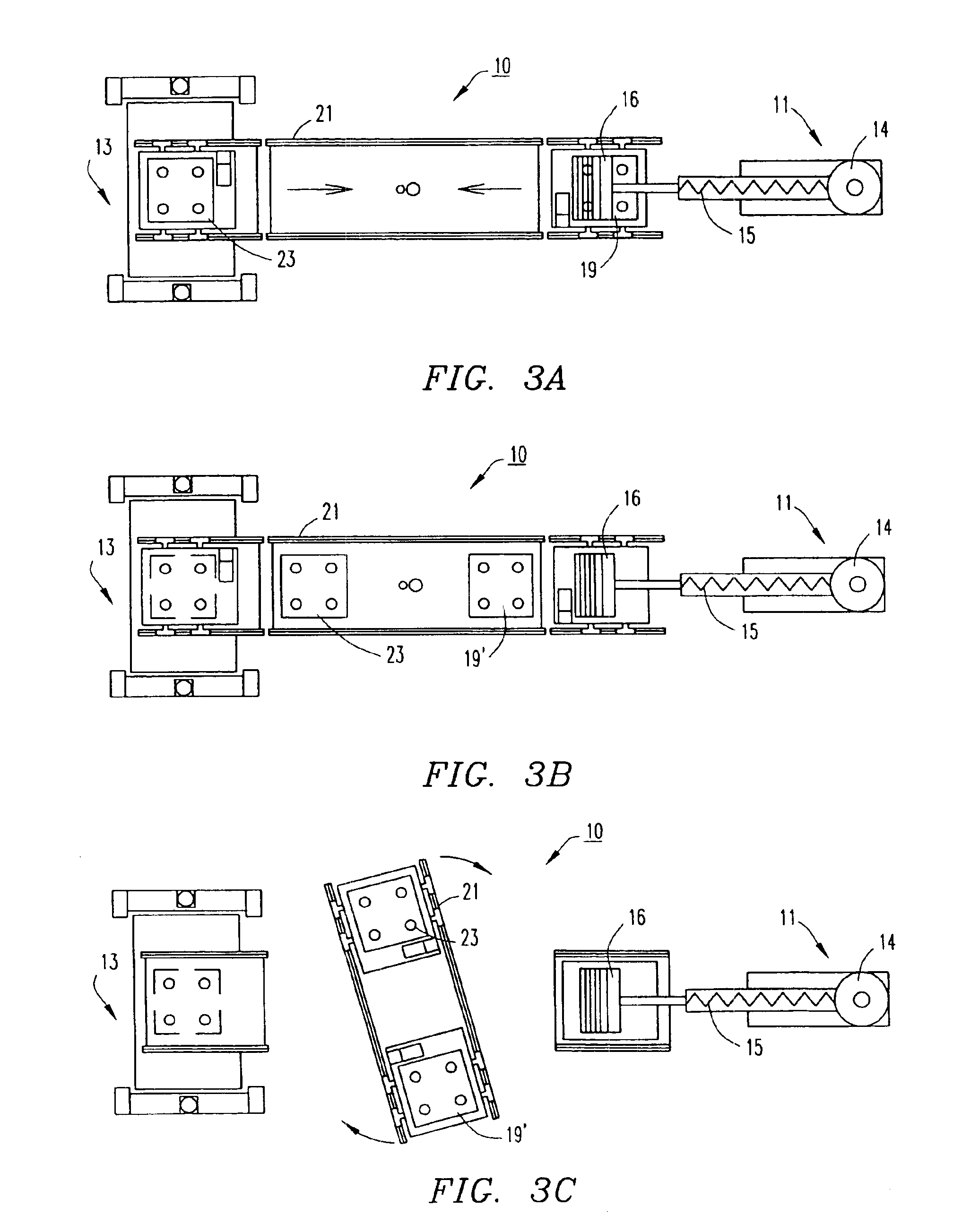
[0052]Referring to FIGS. 1 and 2 of the drawings, a thermoforming apparatus 10 for thermoforming parts from a thermoplastic resin or from a thermoplastic composite is illustrated having an extruder 11, a mold exchange station 12, and a compression mold station 13. The extruder has a hopper 14 mounted on top for feeding a thermoplastic resin or composite material int...


PUM

PropertyMeasurementUnit
lengthaaaaaaaaaa
lengthaaaaaaaaaa
lengthaaaaaaaaaa

Abstract

A system and method for forming an article from thermoplastic material and fiber. The method includes heating thermoplastic material to form a molten thermoplastic material for blending with the fiber. The molten thermoplastic material is blended with the fibers to form a molten composite material having a concentration of fiber by weight. The molten composite material may then be extruded through dynamic dies to deliver discrete controlled material that is gravitated onto a lower portion of a mold. The lower portion of the mold may be moved in space and time while receiving the flow of composite material to deposit a predetermined quantity of molten composite material thereon conforming to mold cavities of the lower and an upper portion of the mold. The upper portion of the mold may be pressed against the predetermined quantity of molten composite material and closing on the lower portion of the mold to form the article.

Description

CROSS-REFERENCE TO RELATED APPLICATIONS[0001]This Application is a divisional of application Ser. No. 10 / 293,005, filed Nov. 13, 2002, which is a continuation-in-part of application Ser. No. 10 / 104,394, filed Mar. 25, 2002, now U.S. Pat. No. 6,719,551, which is a divisional of application Ser. No. 08 / 993,516, filed Dec. 18, 1997, now abandoned.BACKGROUND OF THE INVENTION[0002]1. Field of the Invention[0003]The present invention relates to a thermoplastic molding process and apparatus and especially to a thermoplastic process and apparatus using a proprietary dynamic gated die having adjustable gates for varying the thickness of the extruded material, which material is molded as it is passed from the extrusion die.[0004]2. Description of the Related Art[0005]In the past it has been common to provide a wide variety of molding systems including the molding of a thermoplastic resin or a thermoplastic composite part. In vacuum molding, a slab (constant thickness sheet) of heated thermopl...

Claims


Application Information

Patent Timeline
Patent Type & Authority Patents(United States)
IPC IPC(8): B29C43/34B29C47/92B29C47/16B29C69/02B29C70/04B29C70/46B29C33/00B29C33/34B29C43/04B29C47/10B29C43/02B29C48/07B29C48/12B29C48/31B29C48/92
CPCB29C31/047B29C43/021B29C43/04B29C43/34B29C47/0038B29C47/0816B29C47/16B29C47/92B29C70/46Y10T428/2457B29C33/34B29C47/0014B29C47/0019B29C47/003B29C47/004B29C47/0054B29C47/0057B29C47/0066B29C47/10B29C47/1045B29C2043/046B29C2043/3433B29C2043/3444B29C2043/3488B29C2947/92019B29C2947/92076B29C2947/92085B29C2947/9218B29C2947/92209B29C2947/92542B29C2947/92571B29C2947/9258B29C2947/926B29C2947/92647B29C2947/92657B29C2947/92704B29C2947/92885B29C2947/92904B29C2947/92933B29C2947/92952B29C2947/92961B29K2105/06B29K2105/12B29L2007/002B29L2031/7178B29L2031/732B29C47/1081Y10T428/24124B29C31/048B29C48/92B29C2948/92209B29C48/05B29C2948/92704B29C48/297B29C48/07B29C48/12B29C48/001B29C48/0011B29C48/0017B29C48/0018B29C48/0022B29C48/2556B29C48/285B29C48/2886B29C48/31B29C2948/92019B29C2948/92076B29C2948/92085B29C2948/9218B29C2948/92542B29C2948/92571B29C2948/9258B29C2948/926B29C2948/92647B29C2948/92657B29C2948/92885B29C2948/92904B29C2948/92933B29C2948/92952B29C2948/92961Y10T428/249924B32B3/06B32B37/10
Inventor POLK JR., DALE E.POLK, SR., DALE E.
Owner D&D MFG LLC
Why Eureka
Try Eureka