Motor control circuit for mirror device
a technology of motor control circuit and mirror device, which is applied in the direction of motor/generator/converter stopper, dynamo-electric converter control, instruments, etc., can solve the problems of large circuit scale and complicated circuit configuration, and achieve the effect of reliably stopping the mirror and simple configuration
- Summary
- Abstract
- Description
- Claims
- Application Information
AI Technical Summary
Benefits of technology
Problems solved by technology
Method used
Image
Examples
first embodiment
Configuration of First Embodiment
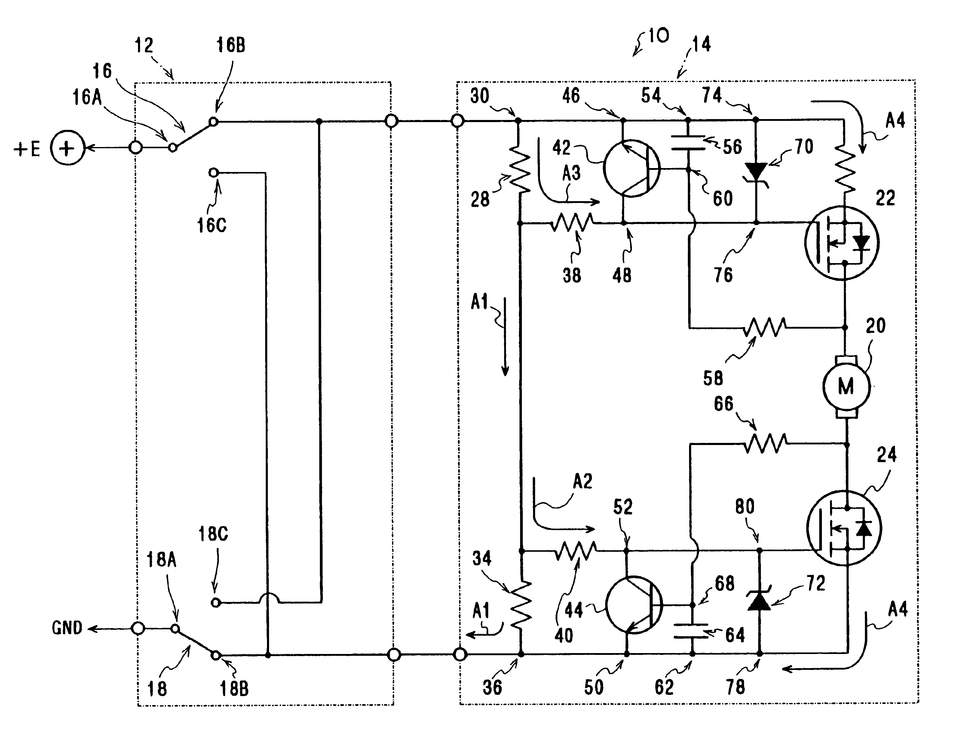
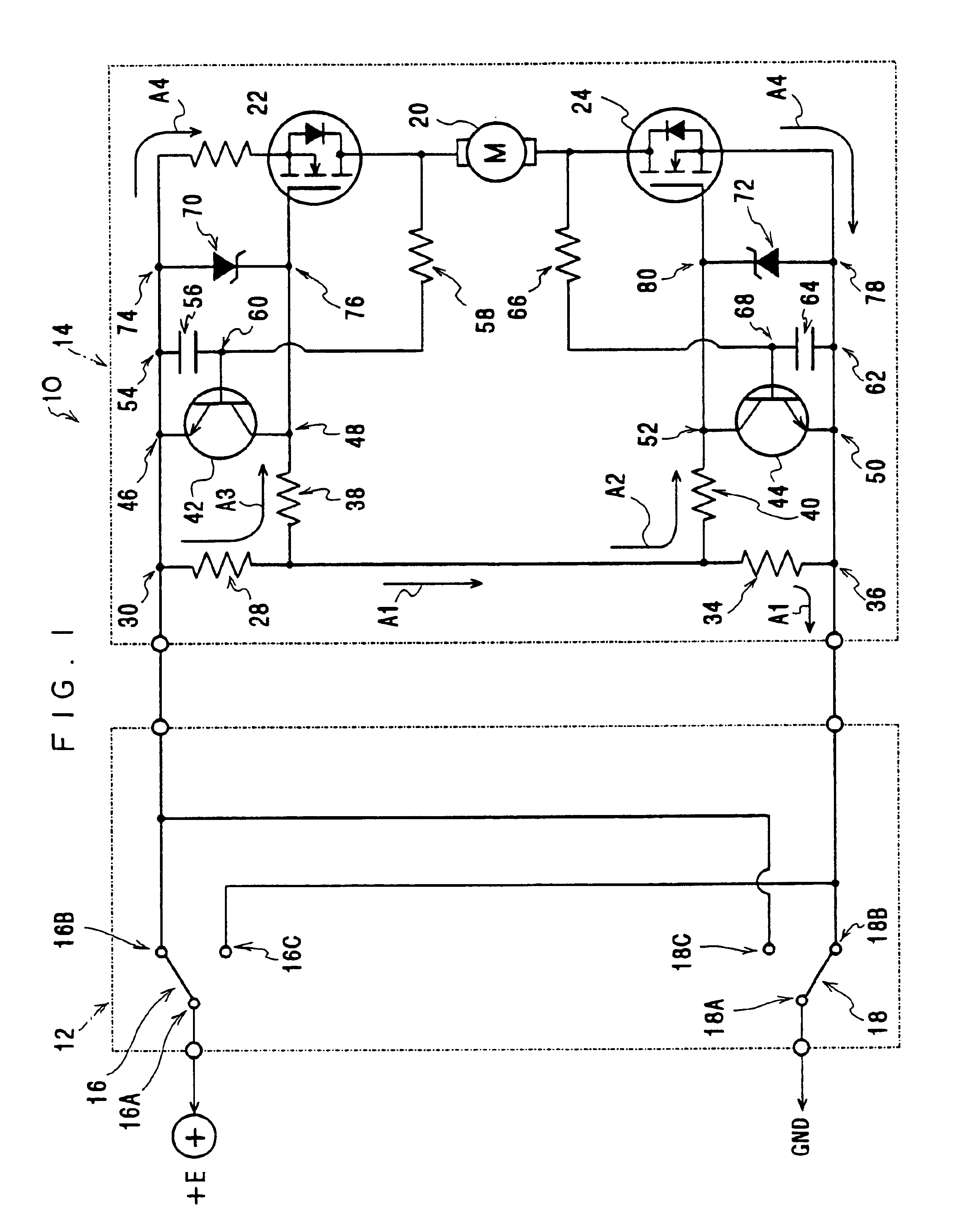
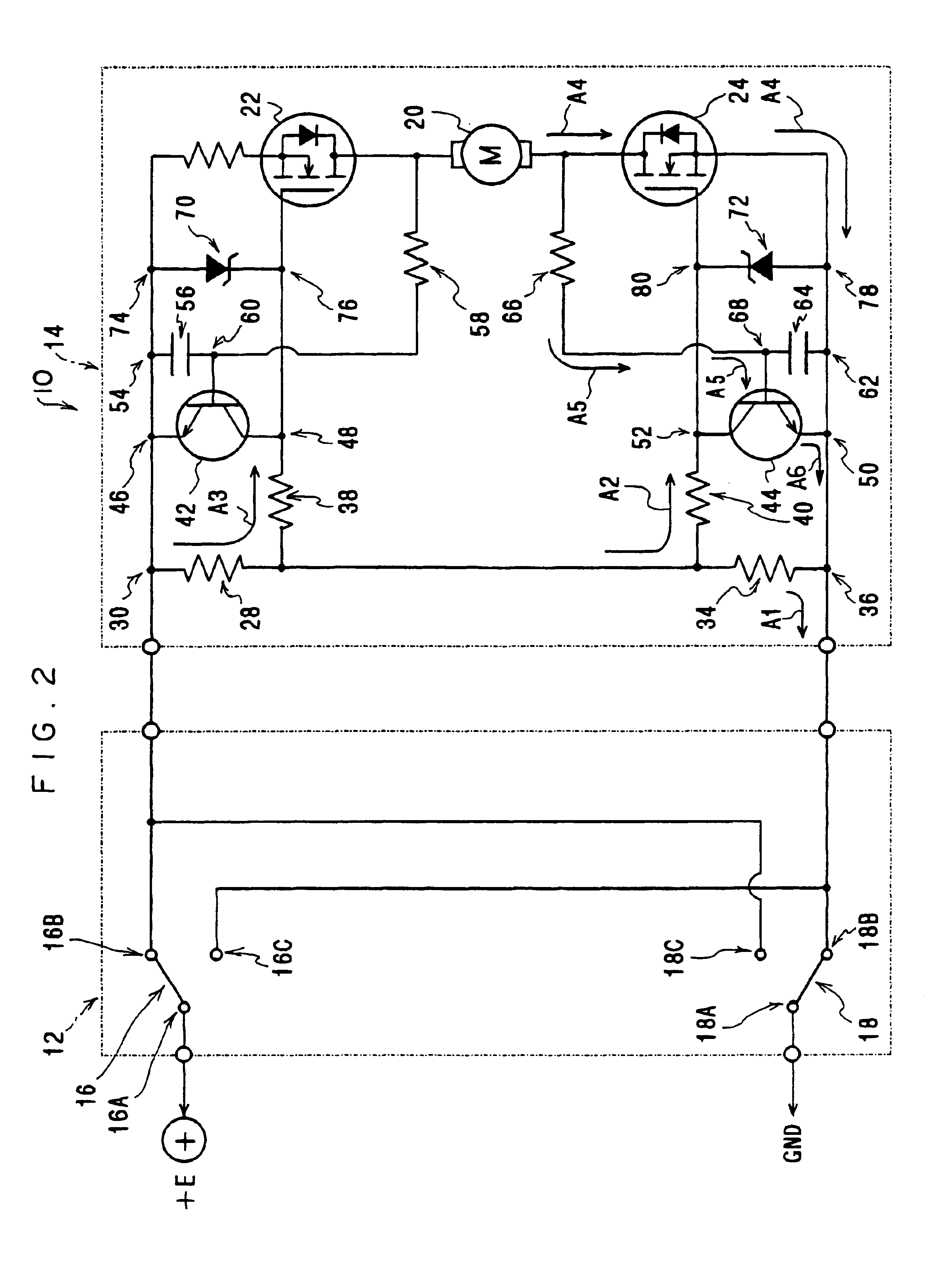
[0049]In FIG. 1, the configuration of a mirror device motor control circuit 10 (referred to below simply as “the control circuit 10”) pertaining to a first embodiment of the invention is illustrated by a circuit diagram.
[0050]As illustrated in this diagram, the present control circuit 10 is disposed with a switch section 12 and a drive control section 14. The switch section 12 is disposed with a pair of switches 16 and 18. The switch 16 is disposed with three terminals 16A, 16B and 16C, and is configured so that one of between the terminal 16A and the terminal 16B and between the terminal 16A and the terminal 16C is placed in a conductive state and the other is placed in a disconnected state.
[0051]The switch 18 is similarly disposed with three terminals 18A, 18B and 18C, and is configured so that one of between the terminal 18A and the terminal 18B and between the terminal 18A and the terminal 18C is placed in a conductive state and the other is plac...
second embodiment
[0080]Next, other embodiments of the invention will be described. It should be noted that, for the purpose of describing the embodiments below, the same reference numerals will be given to parts that are fundamentally the same as those in embodiments preceding the embodiment being described, including the first embodiment, and that description of those parts will be omitted.
[0081]In FIG. 5, a circuit diagram of a mirror device motor control circuit 90 (referred to below simply as “the control circuit 90”) pertaining to a second embodiment of the invention is illustrated.
[0082]As illustrated in this diagram, a drive control section 91 of the present control circuit 90 is disposed with a capacitor 92 serving as a storage terminal. An end of the capacitor 92 is connected between the resistor 28 and the resistor 38, and the other end of the capacitor 92 is connected between the resistor 34 and the resistor 40.
[0083]Because the present control circuit 90 disposed with the capacitor 92 in...
third embodiment
Configuration of Third Embodiment
[0088]Next, a third embodiment of the invention will be described.
[0089]In FIG. 7, the configuration of a mirror device motor control circuit 100 (referred to below simply as “the control circuit 100”) pertaining to the present embodiment of the invention is illustrated by a circuit diagram.
[0090]As illustrated in this diagram, in the present control circuit 100, in contrast to the control circuit 10 pertaining to the first embodiment, a resistor 102 is disposed between the contact point 74 and the drain terminal of the MOSFET 22, and a resistor 104 is disposed between the contact point 78 and the drain terminal of the MOSFET 24.
[0091]Also, the resistors 38 and 40 are not disposed in the control circuit 100, the other end of the resistor 28 and the contact point 48 are directly connected, and the other end of the resistor 34 and the contact point 52 are directly connected.
[0092]Moreover, a diode 106 is disposed between the contact point 48 and the co...
PUM
 Abstract
Description
Claims
Application Information
 - R&D
- Intellectual Property
- Life Sciences
- Materials
- Tech Scout
- Unparalleled Data Quality
- Higher Quality Content
- 60% Fewer Hallucinations
Browse by: Latest US Patents, China's latest patents, Technical Efficacy Thesaurus, Application Domain, Technology Topic, Popular Technical Reports.
© 2025 PatSnap. All rights reserved.Legal|Privacy policy|Modern Slavery Act Transparency Statement|Sitemap|About US| Contact US: help@patsnap.com


