Liquid crystal display

a technology of liquid crystal display and display screen, which is applied in the direction of liquid crystal compositions, instruments, chemistry apparatus and processes, etc., can solve the problems of insufficient brightness, inability to obtain satisfactory display, and low contrast ratio, so as to prevent washout, small power consumption, and excellent visibility

Inactive Publication Date: 2005-05-31
SHARP KK
View PDF25 Cites 62 Cited by
  • Summary
  • Abstract
  • Description
  • Claims
  • Application Information

AI Technical Summary

Benefits of technology

[0021]To apply the above two display methods (a) and (b) which eliminate the parallax to the liquid crystal displays of the transflective type, the reflection layer is provided to touch or almost touch the liquid crystal layer, and a transmission opening is made through the reflection layer to use the transmitted light for the display in addition to the reflected light.
[0052]According to the above arrangement, it has become possible to provide a liquid crystal display with excellent visibility, capable of showing a high-resolution color display while using both the reflected light and transmitted light for the display.

Problems solved by technology

Then, the study revealed the following problems In case of (a) GH method, when a concentration of the dichroic dye blended with the liquid crystal composition is adjusted adequately for the reflection display, the brightness is sufficiently high but the contrast ratio becomes too low in the transmission display section, thereby failing to obtain satisfactory display.
On the other hand, when a concentration of the dichroic dye blended with the liquid crystal composition is adjusted adequately for the transmission display, the contrast ratio is sufficiently high in the transmission display section, but the brightness becomes too low in the reflection display section, thereby failing to obtain satisfactory display.

Method used


Image

  • Liquid crystal display
  • Liquid crystal display
  • Liquid crystal display

Examples


embodiment 1

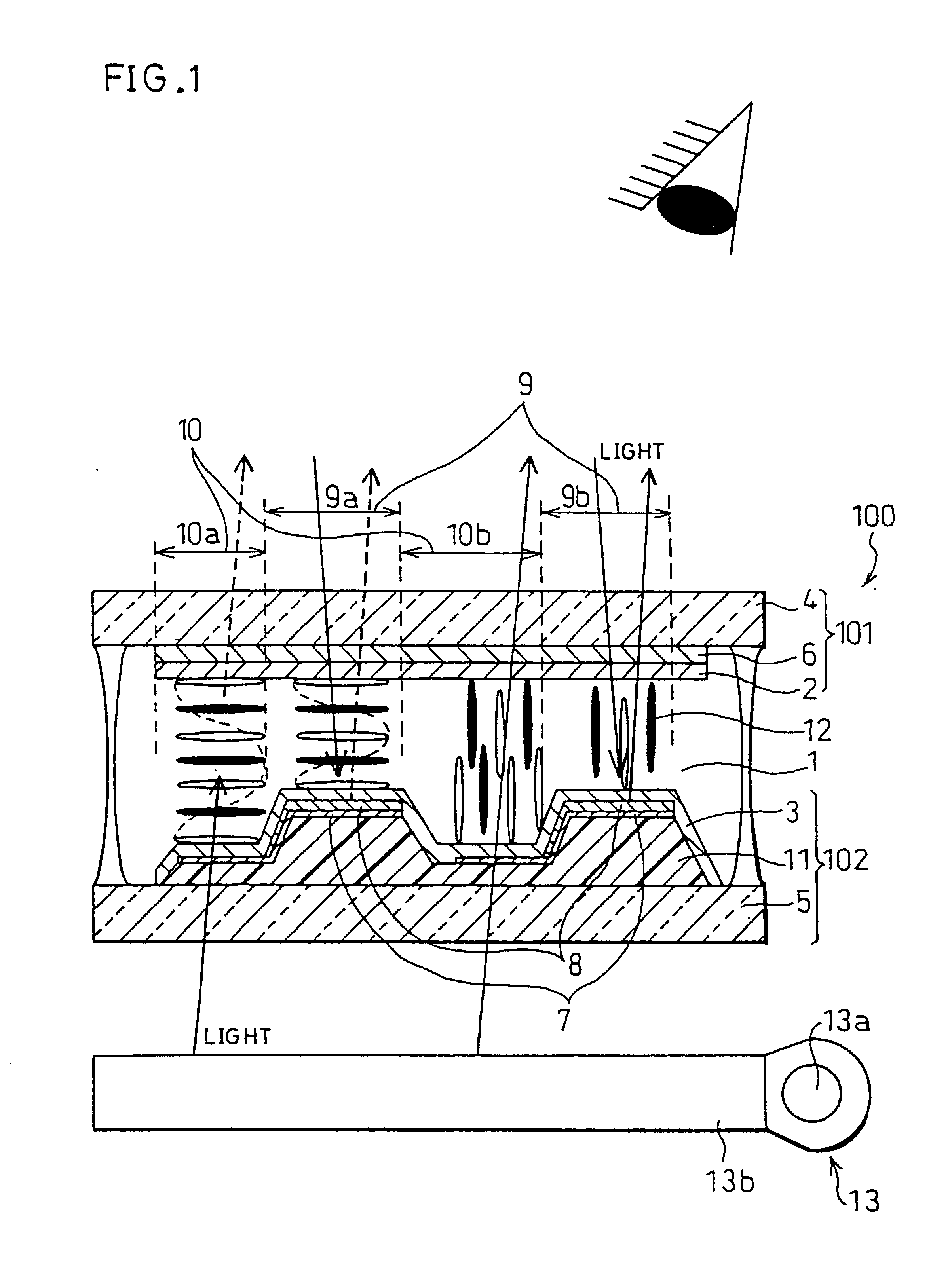
[0117]Mainly referring to FIG. 1, an example liquid crystal display adopting the Δn method will be explained in the present embodiment.

[0118]FIG. 1 is a cross section of a major portion of the liquid crystal display in accordance with the present embodiment. As shown in the drawing, the liquid crystal display includes a liquid crystal cell 100 (liquid crystal display element), and optionally, a back light 13 (lighting device) serving as back light means. The liquid crystal cell 100 and back light 13 are provided sequentially in this order from the viewer's (user's) side.

[0119]As shown in the drawing, the liquid crystal cell 100 is composed of a liquid crystal layer 1 sandwiched by an electrode substrate 101 (first substrate) and an electrode substrate 102 (second substrate). The electrode substrate 101 has an alignment film 2 on a surface touching the liquid crystal layer 1 (an interface between the first substrate and the liquid crystal layer 1), and the electrode substrate 102 has...

example 1

[0149]Explained in the present example is a liquid crystal display employing the liquid crystal layer 1 adopting the GH method, in which the liquid crystal having the negative dielectric constant anisotropy aligns substantially perpendicular to the display surface when no voltage is applied to the liquid crystal layer 1 and tilts with respect to the display normal when a voltage is applied to the liquid crystal layer 1. First, the following will explain a method of manufacturing the liquid crystal display.

[0150]Initially, a 140 nm-thick ITO film is sputtered over the transparent substrate 4, which is etched by photolithography, whereby the electrode 6 (transparent electrode) of a predetermined pattern is formed. Here, a glass substrate is used as the substrate 4.

[0151]Next, a vertical aligning alignment film is provided to the substrate 4 by the offset printing on the surface where the electrode 6 is formed, and the substrate 4 is baked at 200° C. in an oven, whereby the alignment f...

embodiment 2

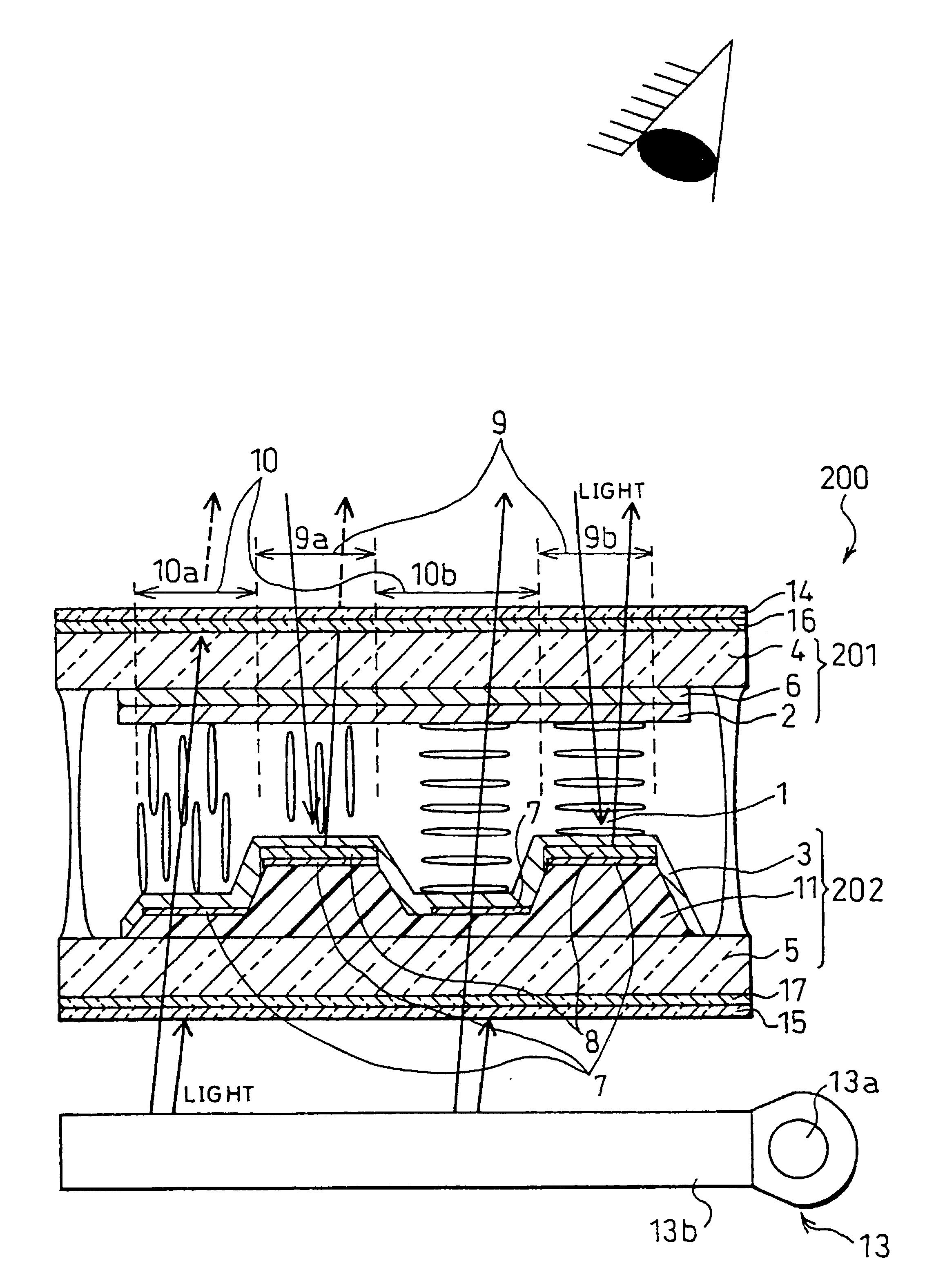
[0172]The liquid crystal display of Embodiment 1 adopts the GH method, but liquid crystal displaying methods other than the GH method are also applicable. For example, another applicable method is shown in FIG. 4, in which the substrates 4 and 5 are sandwiched by polarization plates 14 and 15, so that the retardation or optical rotatory polarization (which are collectively referred to as polarization converting function) of the liquid crystal layer 1 is used for the display.

[0173]In the present embodiment, a liquid crystal display using the polarization converting function will be explained with reference to FIG. 4 mainly. Hereinafter, like components are labeled with like reference numerals with respect to Embodiment 1, and, for ease of explanation, the description of these components is not repeated here.

[0174]FIG. 4 is a cross section showing a major portion of the liquid crystal display of the present embodiment. The liquid crystal display of FIG. 4 includes a liquid crystal cel...


PUM


Abstract

A liquid crystal display is furnished with: a liquid crystal display element having a pair of substrates, to which alignment members are provided to their respective opposing surfaces, and a liquid crystal layer sandwiched by the pair of substrates; an alignment mechanism for providing at least two different director configurations simultaneously on different arbitrary regions used for display in the liquid crystal layer; and a reflection film provided to at least one of the different arbitrary regions showing different director configurations; wherein the different arbitrary regions showing different director configurations are used for a reflection display section for showing reflection display and a transmission display section for showing transmission display, respectively. Examples of the alignment mechanism include an alignment film to which the alignment treatment is applied in different orientations in the reflection display section and transmission display section, respectively, an insulation film having different film thicknesses in the reflection display section and transmission display section, and so forth.

Description

[0001]This application is a divisional of co-pending application Ser. No. 09 / 887,442, filed on Jun. 25, 2001, now U.S. Pat. No. 6,563,554 which is a divisional of application Ser. No. 09 / 217,931 filed on Dec. 22, 1998, now U.S. Pat. No. 6,281,952 the entire contents of which are hereby incorporated by reference and for which priority is claimed under 35 U.S.C. §120; and this application claims priority of Application No. 9-359036 and 10-364247 filed in Japan on Dec. 26, 1997 and Dec. 22, 1997, respectively under 35 U.S.C. §119.FIELD OF THE INVENTION[0002]The present invention relates to liquid crystal displays used for information systems, such as word processors and notebook-type personal computers, video equipment of various kinds, video game machines, portable VCRs, digital cameras, etc. More particularly, the present invention relates to liquid crystal displays used indoors and outdoors, or in automobiles, air-planes, marine vessels, etc. where a variety of ambient light conditi...

Claims


Application Information

Patent Timeline
Patent Type & Authority Patents(United States)
IPC IPC(8): G02F1/1335G02F1/13G02F1/1333G02F1/1337G02F1/1343
CPCG02F1/133514G02F1/133555G02F1/133371G02F2202/04G02F1/133753G02F2001/133638G02F1/133638
Inventor OKAMOTO, MASAYUKIHIRAKI, HAJIMEMITSUI, SEIICHI
Owner SHARP KK
Why Eureka
Try Eureka