Wide field-of-view (FOV) coherent beam combiner/detector

Inactive Publication Date: 2005-05-31
GENERAL DYNAMICS MISSION SYST INC
View PDF26 Cites 2 Cited by
  • Summary
  • Abstract
  • Description
  • Claims
  • Application Information

AI Technical Summary

Benefits of technology

[0009]Broadly, this invention removes the small FOV limitation of current coherent beam combiner technology, and enables beam combining over significa

Problems solved by technology

That is, while the total FOV of the system allows receiving radiation over large angles, coherent combining is limited to a very small neighborhood (=coherent FOV) of that particular direction within the total FOV.
Even if fibers are used, the collection area is so sm

Method used


Image

  • Wide field-of-view (FOV) coherent beam combiner/detector
  • Wide field-of-view (FOV) coherent beam combiner/detector
  • Wide field-of-view (FOV) coherent beam combiner/detector

Examples


Embodiment Construction

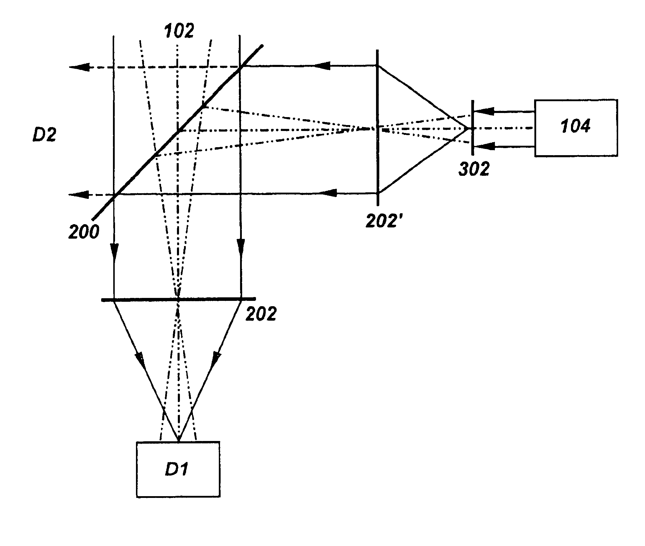
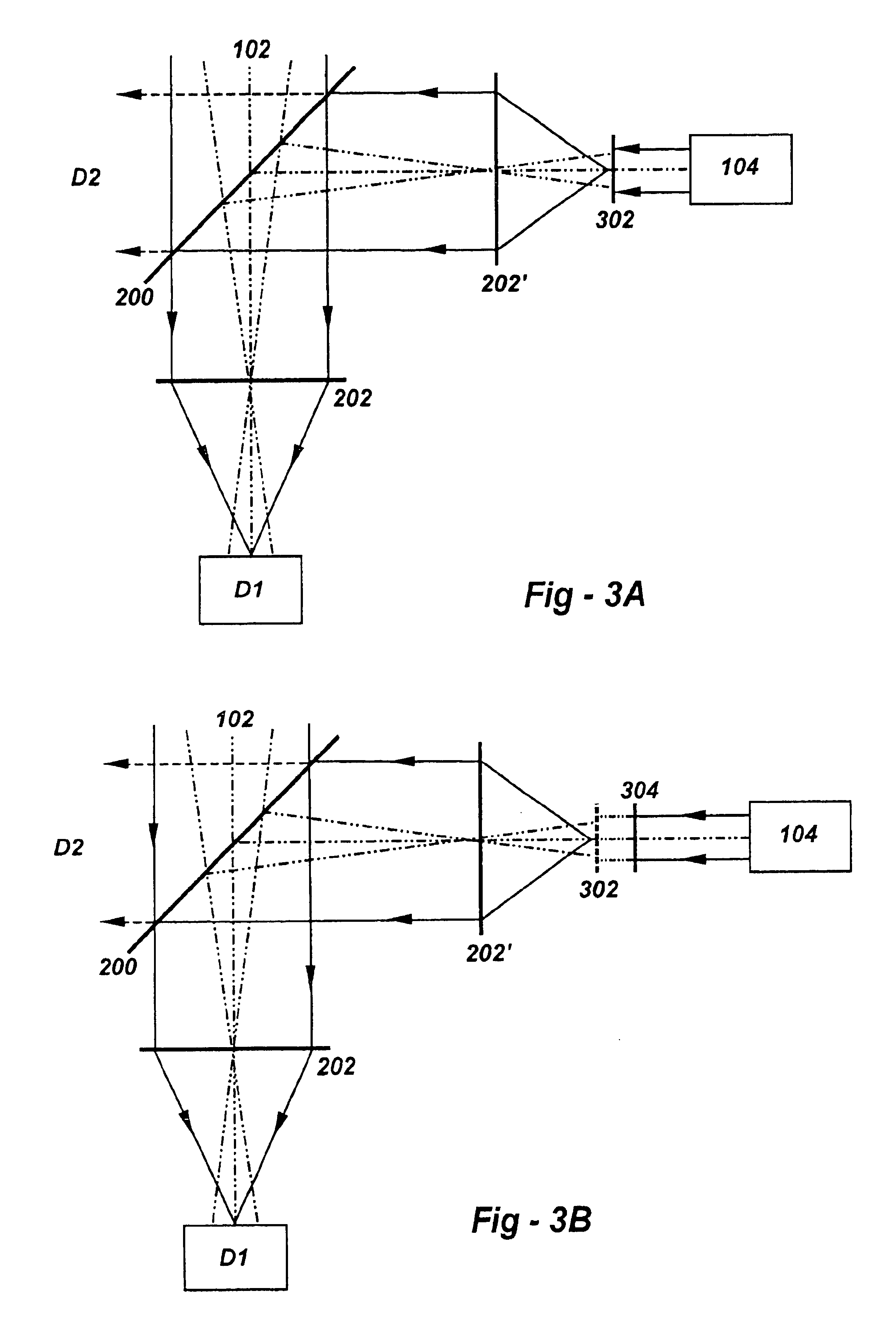
[0018]Two different implementations are shown in FIGS. 3(a) and 3(b). Referring to FIG. 3(a), the local oscillator wave front illuminates a diffuser 302, different points of which effectively behave as point sources of the local oscillator. The signals from these point sources are coherent but with a temporally fixed, spatially random phase difference between the points. While this introduces a delay error, this error is insignificant in applications such as optical communication systems and laser radar systems. In laser radar systems, for example, this phase error will result in a range error equivalent to the optical path difference corresponding to the optical thickness variations in the diffuser, which is less than a few tens of microns. In communication systems, this delay error is so small (˜1013 sec) that it does not cause any synchronization problems. Thus, for any direction in the receiver FOV there is a local oscillator wave front, which makes coherent combining possible. ...


PUM


Abstract

The small field-of-view (FOV) limitation of current coherent beam combiner technology is overcome, enabling beam combining over significantly larger fields of view. The system includes an input to receive an input wavefront, a local oscillator to generate a reference wavefront, and an optical combiner such as a beam splitter to combine the input wavefront and the reference wavefront to produce an output wavefront which is received by a detector. According to the invention, an optical element is supported to receive the reference wavefront and generate, in effect, a plurality of local oscillator point sources which provide a set of wavefronts that cover the required wider FOV. In the preferred embodiment, the optical element is a diffuser, and may optionally include a mechanism for rotating the diffuser to reduce speckle. In an alternative embodiment the optical element is a lenslet array. The spacing of the lenslets in the array is preferably such that the angle subtended by centers of two adjacent lenslets as seen from the center of the system's collimating lens or mirror is less than 0.83λ/D, where λ is the wavelength of the radiation, and D is the aperture diameter. This invention finds utility in any application which uses coherent beam combining, including optical communication systems, laser radar systems, and other fields of endeavor.

Description

FIELD OF THE INVENTION[0001]This invention relates generally to coherent beam combining and, in particular, to apparatus and methods for increasing the field-of-view (FOV) in such systems.BACKGROUND OF THE INVENTION[0002]Coherent beam combiners are useful in many applications, including optical communications and laser radar. An overall receiver system, of which the beam combiner 100 is a part, is shown in FIG. 1. Radiation from an object space 102 typically enters through a mechanical scanner (not shown) before interacting the combiner itself, which merges the received wavefront with the signal from a local oscillator 104. In the balanced detection scheme, two detectors D1, D2 are used as shown, for better signal to noise ratio, for any given line of sight in the wide field of view. Using current technology, coherent beam combining is limited to the coherent field of view (FOV), given by 1.63λ / D, where λ is the wavelength of the radiation, and D is the aperture diameter. For exampl...

Claims


Application Information

Patent Timeline
IPC IPC(8): G02B27/48G02B27/50G02B27/52
CPCG02B27/52G02B27/48
Inventor GULLAPALLI, SARMA N.
Owner GENERAL DYNAMICS MISSION SYST INC
Why Eureka
Try Eureka