Automatic sound field correcting device

a sound field correction and automatic technology, applied in the direction of electrical transducers, gain control, instruments, etc., can solve the problems of difficult for a listener to appropriately adjust, phase of the signal of multiple channels mismatching, reproduced sound image not correctly located at the center of left and right, etc., to achieve high-quality sound field space and reduce adverse effects

Inactive Publication Date: 2005-05-31
PIONEER CORP
View PDF9 Cites 18 Cited by
  • Summary
  • Abstract
  • Description
  • Claims
  • Application Information

AI Technical Summary

Benefits of technology

[0010]It is an object of the present invention to provide an automatic sound field correcting device that can provide high quality sound field space by reducing the adverse effect resulting from the phase mismatch between signals from multiple speakers.
[0012]In accordance with the automatic sound field correcting device thus configured, a plurality of audio signals to be reproduced by a plurality of speakers are input, and the signal processing is applied on the corresponding signal transmission paths. The measurement signal is supplied to the respective signal transmission paths, and output by the corresponding speakers. The sound of the output measurement signal is collected and the detection signal of the collected sound is generated. The equalizer gain values are determined based on the detection signals. By determining the identical equalizer gain values for the plural signal transmission paths for which the phases of the audio signals are to be matched, the phases of the signals on those signal transmission paths are matched, and the strange auditory feeling can be reduced.
[0017]The plurality of signal transmission paths for which the phases of the audio signal are to be matched may include a pair of signal transmission paths corresponding to a pair of left and right speakers. In addition, the pair of left and right speakers may include at least one of front speakers, rear speakers and surround speakers. By this, the phase mismatch between the left and the right speakers may be avoided, and the strange auditory feeling may also be avoided.
[0019]The gain value determining unit may determine the identical equalizer gain value by averaging the equalizer gain values determined individually for each of the signal transmission paths for which the phases of the audio signals are to be matched. By this, the influence of the phase mismatch can be eliminated by the simple averaging process.
[0021]The measurement signal supplying unit may generate the measurement signals which correspond to the signal transmission paths and which have no correlation with each other. Thus, frequency characteristics can be adjusted more accurately.
[0022]The automatic sound field correcting device may further include a plurality of delay circuits each provided in the signal transmission path for adjusting delay characteristics of the audio signals, and the measurement signal supplying unit may generate the measurement signals having no correlation by setting different delay times for the plurality of delay circuits. By this, the measurement signal having no correlation can be generated by using the delay circuit that is used for the delay Gus characteristics correction, and hence the frequency characteristics can be accurately corrected without complicated configuration.

Problems solved by technology

In other words, it is required for the audio system to automatically correct sound field characteristics because it is quite difficult for a listener to appropriately adjust the phase characteristic, the frequency characteristic, the sound pressure level and the like of sound reproduced by a plurality of speakers by manually manipulating the audio system by himself to obtain appropriate sound field space.
However, if the frequency characteristics of the equalizers are controlled independently for the multiple channels, the phases of the signals of the multiple channels mismatch because the phases of the signals vary when different equalizer coefficients are used for different channels.
However, if the audio signals of the left and right channels are out of phase with each other (i.e., mismatch), the reproduced sound image does not correctly locate at the center of the left and right speakers, and the listener acoustically feels like the sound source is at other position.
Therefore, if the audio signals from the left and right speakers are out of phase, the listener feels the reproduced sound coming from unnatural direction and may have strange auditory feeling.
If the phases of the signals from the pair of the speakers mismatch, correct phantom sound image cannot be created, and the listener feels more strange.
This prevents correct sound field reproduction, and consequently damages the presence of the sound field.

Method used


Image

  • Automatic sound field correcting device
  • Automatic sound field correcting device
  • Automatic sound field correcting device

Examples


modified embodiment

[3] Modified Embodiment

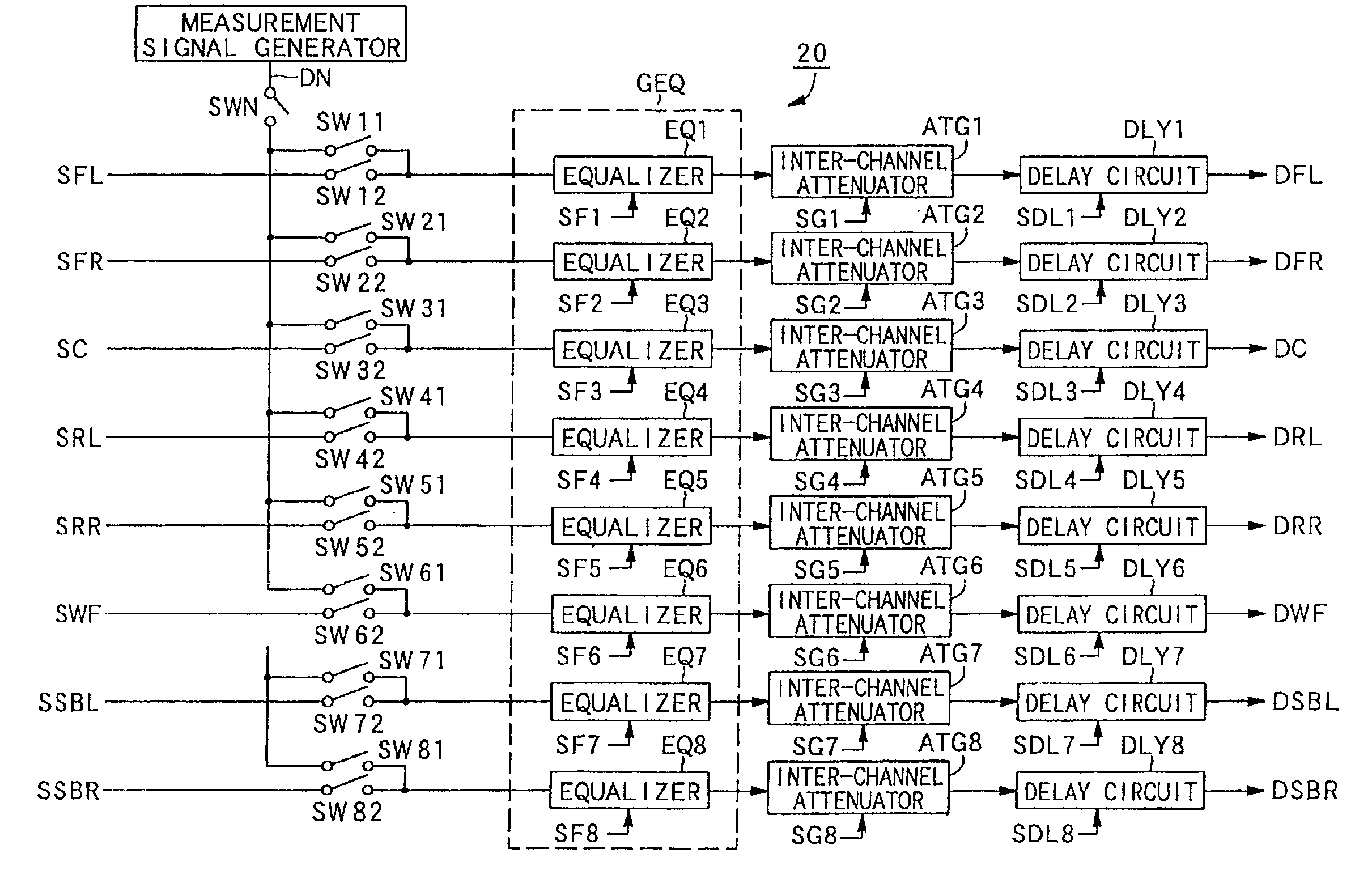
[0090]Next, the modified embodiment of the present invention will be described. In the embodiment described above, the frequency characteristics are corrected simultaneously for multiple channels belonging to the identical phase group, thereby to avoid the adverse effect resulting from the phase mismatch. However, as mentioned above, there is a trade-off relation between the prioritization of the phase match and the prioritization of adjusting the frequency characteristics of the respective channels to desired characteristics, and it is necessary to determine which one should be put higher priority in consideration of the environment in which this audio system is placed and other factors. Therefore, it is advantageous if the listener can determine which one is more important.

[0091]In this view, in the following modified embodiment, the gain adjustment amounts SF of the equalizers EQ of the respective channels obtained by the method in which the frequency chara...


PUM


Abstract

In the automatic sound field correcting device, a plurality of audio signals to be reproduced by a plurality of speakers are input, and the signal processing is applied on the corresponding signal transmission paths. The measurement signal is supplied for the respective signal transmission paths, and output by the corresponding speakers. The sound of the output measurement signal is collected and the detection signal of the collected sound is generated. The equalizer gain values are determined based on the detection signals. By determining the identical equalizer gain values for the plural signal transmission paths for which the phases of the audio signals are to be matched, the phases of the signals on those signal transmission paths are matched, and the strange auditory feeling due to the phase mismatch can be reduced.

Description

BACKGROUND OF THE INVENTION[0001]1. Field of the Invention[0002]This invention relates to an automatic sound field correcting device for automatically correcting sound field characteristics in an audio system having a plurality of speakers.[0003]2. Description of Related Art[0004]For an audio system having a plurality of speakers to provide a high quality sound field space, it is required to automatically create an appropriate sound field space with much presence. In other words, it is required for the audio system to automatically correct sound field characteristics because it is quite difficult for a listener to appropriately adjust the phase characteristic, the frequency characteristic, the sound pressure level and the like of sound reproduced by a plurality of speakers by manually manipulating the audio system by himself to obtain appropriate sound field space.[0005]An audio system of this kind is disclosed in a Japanese utility model application laid-open under 6-13292. This au...

Claims


Application Information

Patent Timeline
Patent Type & Authority Patents(United States)
IPC IPC(8): H04S7/00H04S3/00G10K15/00H04S5/02
CPCH04S7/301H04S3/00H04S7/307
Inventor YOSHINO, HAJIMETSUKADA, KAZUYA
Owner PIONEER CORP
Why Eureka
Try Eureka