Control of externally induced current in an implantable pulse generator

a pulse generator and external current technology, applied in electrotherapy, therapy, etc., can solve the problems of false “sensing” response, unsatisfactory tissue stimulation in the patient, shock to the patient, etc., to improve ipg emc compatibility, reduce effective surface area, and reduce effective surface area

Inactive Publication Date: 2005-05-31
MEDTRONIC INC
View PDF18 Cites 162 Cited by
  • Summary
  • Abstract
  • Description
  • Claims
  • Application Information

AI Technical Summary

Benefits of technology

[0013]In still another embodiment, the IPG system may operate in a distal unipolar mode to reduce the effective surface area from which unwanted current is induced. The IPG system may include a plurality of leads where each at least one lead is in electrical communication with the signal generator and conveys the electrical signal to the patient and where at least one other lead is coupled to a electrical ground.
[0014]In even enother embodiment, the IPG system may operate in a virtual unipolar mode to reduce the effective surface area from which unwanted current is induced. The IPG system may include a lead having a plurality of electrical conductors that each extend from a p

Problems solved by technology

A user having such an implantable medical device during normal life activities may be forced to go through a time-alternating electromagnetic field.
These induced voltages may be of sufficient voltage and pulse duration to cause undesired tissue stimulation in the patient.
This may result in shocking sensations to the patient, pacing of the heart, IPG sensing irregularities or other undesired stimulation effects.
Additionally, in some medical devices with sensin

Method used


Image

  • Control of externally induced current in an implantable pulse generator
  • Control of externally induced current in an implantable pulse generator
  • Control of externally induced current in an implantable pulse generator

Examples


Embodiment Construction

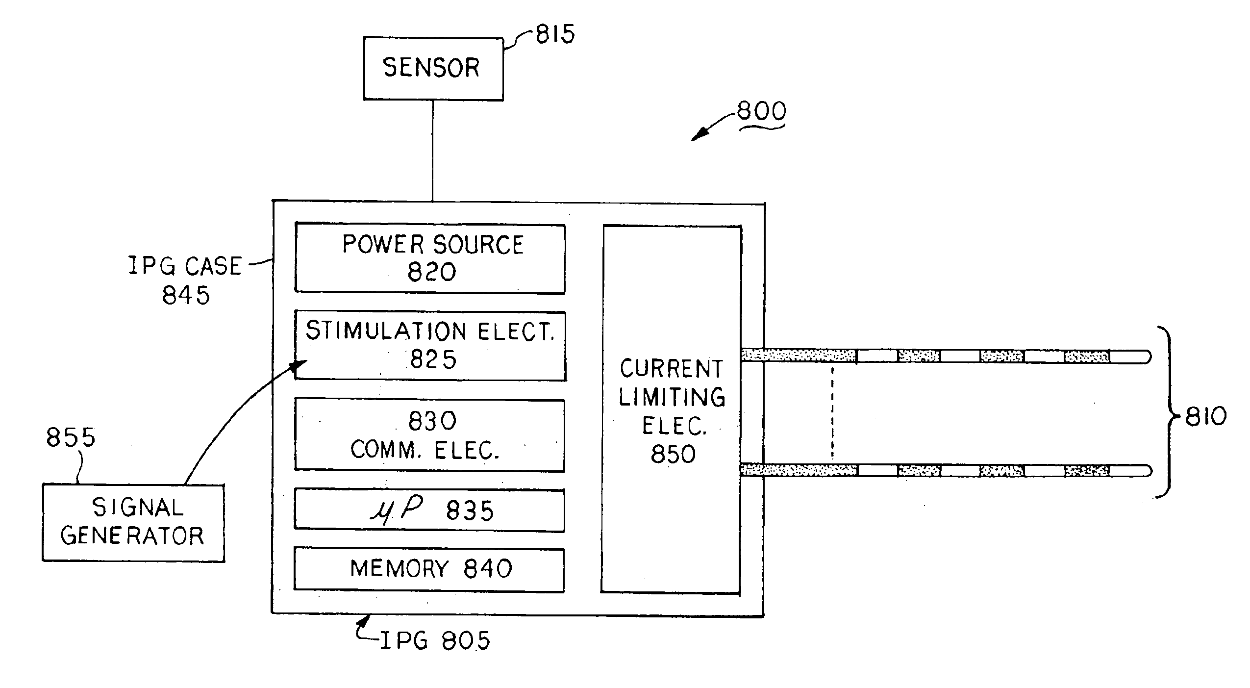
[0028]As exemplified herein, the invention may be embodied in various forms. The present invention is generally a current limiting apparatus and method for limiting current flow, induced when the level of a signal is greater than an external signal threshold signal level, in a conductive loop formed by a medical device implanted within a living organism having electrically excitable tissue.

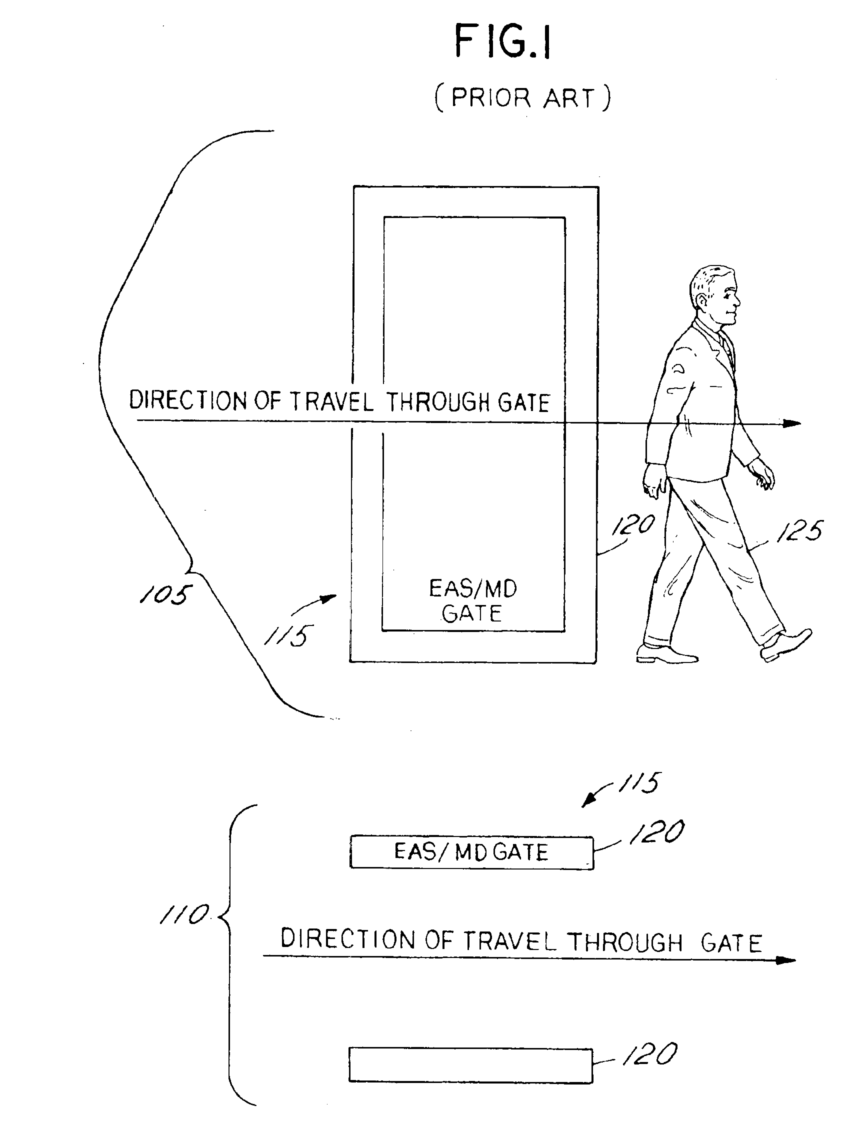
[0029]FIG. 1 illustrates a side view 105 and a top view 110 of a typical installation of an Electronic Article Surveillance (EAS) or Metal Detector (MD) installation 115. Most systems consist of one or more panels 120 located across the entrance and / or exits of the retail businesses or other areas to be protected. As a person 125 passes between the gates, they are subjected to an electromagnetic field that is used to sense the presence of “activated” theft detector tags or the presence of metal objects. If activated tags or metal are detected, an alarm will be generated. MD and EAS systems may als...


PUM


Abstract

The present invention takes the form of a current limiting apparatus and method for limiting current flow, induced when the level of an external signal is greater than an external signal threshold signal level, in a conductive loop formed by a medical device implanted within a living organism having electrically excitable tissue. The system includes an implantable pulse generator (IPG) system having a housing, a signal generator disposed in the housing that generates an electrical signal, and at least one lead extending from the housing to convey electrical signal to the patient. To limit the induced current flow, the IPG includes current limiting componentry, an impedance increasing element, and/or alternating current blocking elements. These components provide an alternating current impedance path to the electrical ground from a lead coupled to the capacitive element. Also disclosed are techniques for reducing the effective surface area of the current inducing loop caused by the IPG system.

Description

[0001]This application claims priority to provisional U.S. Application Ser. No. 60 / 277,076, filed Mar. 19, 2001.FIELD OF THE INVENTION[0002]The invention relates generally to implantable medical devices, and more particularly to a method and apparatus for limiting unwanted current flow through electrically excitable tissue resulting from application of an external signal on an implanted medical device.BACKGROUND OF THE INVENTION[0003]The use of implantable medical devices for electrical stimulation of electrically excitable tissue is well known in the medical arts. For example, electrical stimulation of the brain, the spinal cord, or a peripheral nerve may be used to treat any number of medical conditions. In such devices, electrodes deliver the stimulation of signal to the electrically excitable tissue. The electrodes are operatively connected to an implantable pulse generator (IPG) that is packaged in a case that is adapted to be implantable. Those electrodes are coupled to that p...

Claims


Application Information

Patent Timeline
IPC IPC(8): A61N1/32A61N1/08A61N1/37A61N1/375
CPCA61N1/08A61N1/3754A61N1/32A61N1/3718
Inventor HRDLICKA, GREGORY ANTHONYGRABINGER, SCOTTSTEIN, MARCMUELLER, DAVEWESSELINK, WILBERT
Owner MEDTRONIC INC
Why Eureka
Try Eureka