An exhaust gas pressure regulator for a combustion engine

a technology of exhaust gas pressure regulator and combustion engine, which is applied in the direction of engines, machines/engines, mechanical equipment, etc., can solve the problems of large amplitude oscillation, reduced efficiency, and reduced efficiency of combustion engines, so as to reduce the effective surface area and design robust

Active Publication Date: 2018-05-17
VOLVO LASTVAGNAR AB
View PDF4 Cites 0 Cited by
  • Summary
  • Abstract
  • Description
  • Claims
  • Application Information

AI Technical Summary

Benefits of technology

[0030]According to a further example aspect of the exhaust gas pressure regulator, the regulating piston comprises a sleeve portion in sliding contact with an exterior side of the front portion of the inner diffuser assembly, and the sleeve portion protrudes into the exhaust gas flow duct when the regulating piston is in the pressurized position for at least partly closing the exhaust gas flow duct. Using the sleeve portion for closing the flow path of the exhaust gas flow in the exhaust gas flow duct has the advantage of reducing the effective surface area of the regulating piston that may generate an axial force on the regulating piston towards the closed position. Thereby, any large amplitude pressure pulses within the exhaust gas flow in the exhaust gas flow duct will not transmit any large forces for moving the regulating piston in the axial direction.
[0031]According to a further example aspect of the exhaust gas pressure regulator, the diffuser assembly comprises a stationary shaft, and the regulator piston is slidingly arranged on the shaft. This arrangement enables a robust design of the gas pressure regulator.

Problems solved by technology

As a result, the high-pressure exhaust gas within the exhaust system will generate a relatively large counter force on the top side of the pistons during the exhaust stroke of the piston, such that the combustion engine is forced to slow down.
Such pressure variations will cause the control piston to move back and forth rapidly and the amplitude of the oscillations may become particularly large at those engine combustion frequencies that are associated with the resonance frequency of the control piston.
One example problem caused by large amplitude oscillations of the control piston is damages to control piston and / or regulator housing caused by repeated impact between the control piston and regulator housing at the end stroke of the regulator piston.
Moreover, the oscillation may cause impact between neighbouring laps of a spring coils, thereby resulting in a relaxation problem of the spring and finally fracture damages.
Finally, if a dampening element is provided for dampen said impact, the dampening element itself may become damaged due to the large amplitude oscillations.
With too little throttling effect of the throttled flow passage substantially no pressure averaging effect is obtained by the throttled flow passage, such that relatively large amplitude pressure oscillations will propagate into the exhaust gas pressure chamber and potentially cause the regulating piston to oscillate with high amplitude.
With too high throttling effect an increase in backpressure at the inlet of the exhaust gas pressure regulator caused by a suddenly closed regulating piston may result in a relatively slow increase of the pressure within the exhaust gas pressure chamber, such that the regulating piston too slowly will reach its equilibrium position.
This delay in reaching the equilibrium position might therefore generate excessive back pressure for a certain time period, such that the vehicle brake effect is higher than desired.
Moreover, with too high throttling effect it may also become difficult to quickly change the position of the regulating piston at all, such that a desired backpressure at the inlet of the exhaust gas pressure regulator may temporarily significantly deviate from the actual back pressure.
Such deviation is undesirable because it implies that the engine braking system does not provide as much braking force as desired.
Consequently, either the hydraulic braking system must temporarily compensate for lack of braking force by means of complex regulating systems, or the driver will experience an undesirable inconsistency between vehicle deceleration and brake pedal actuation.
As discussed above, too high attenuation may result in reduced consistency between desired braking performance and actually delivered engine braking performance, and too low attenuation may result in damages to the regulator.

Method used


Image

  • An exhaust gas pressure regulator for a combustion engine
  • An exhaust gas pressure regulator for a combustion engine
  • An exhaust gas pressure regulator for a combustion engine

Examples


Embodiment Construction

[0048]Various aspects of the disclosure will hereinafter be described in conjunction with the appended drawings to illustrate and not to limit the disclosure, wherein like designations denote like elements, and variations of the described aspects are not restricted to the specifically shown embodiments, but are applicable on other variations of the disclosure.

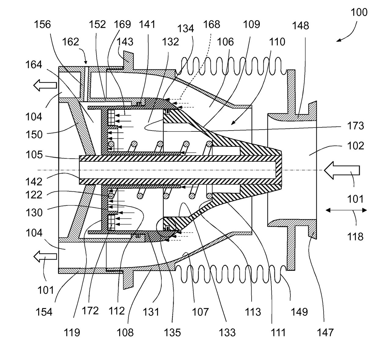
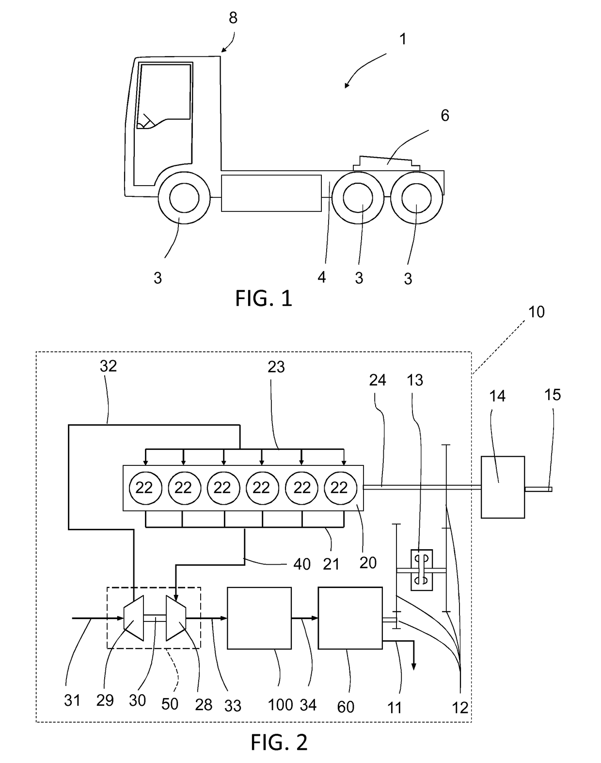
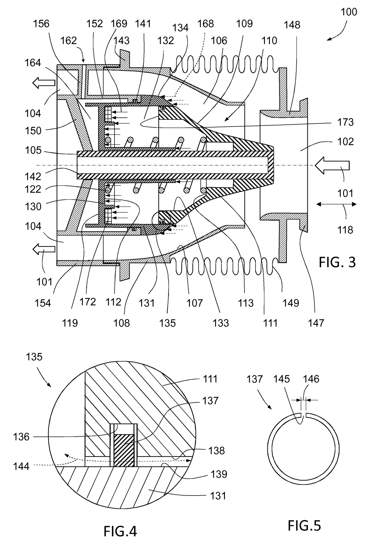
[0049]With reference to FIG. 1, the disclosure concerns an exhaust gas pressure regulator for a combustion engine, wherein the combustion engine for example may be located in a vehicle such as a truck 1 for pulling a trailer. The truck typically comprises a chassis 4, front and rear wheels 3, a driver's cabin 8 and connector device 6 for connecting a trailer vehicle to the truck 1. The combustion engine may however alternatively be installed in other types of vehicles, such as buses, construction machinery, or the like.

[0050]FIG. 2 schematically shows an example embodiment of piston engine 10 having the exhaust gas pressure reg...


PUM


Abstract

An exhaust gas pressure regulator for a combustion engine includes a regulator housing and an inner diffuser assembly arranged inside the regulator housing so that an exhaust gas flow duct is formed between an inner surface of the regulator housing and an outer surface of the inner diffuser assembly. The inner diffuser assembly includes a front portion and a regulating piston that is moveable relative to the front portion and the regulator housing between an idle position in which the exhaust gas flow duct is open, and a pressurized position in which the regulating piston at least partly closes the exhaust gas flow duct. The inner diffuser assembly includes at least one throttled flow passage between the gas flow duct and an exhaust gas pressure chamber defined by the regulating piston and an interior surface of the front portion.

Description

BACKGROUND AND SUMMARY[0001]The present invention relates to an exhaust gas pressure regulator for an engine. More particularly, the present invention relates to an exhaust gas pressure regulator having a moveable regulating member for controlling the exhaust gas through flow. Exhaust gas pressure regulators may be used for controlling a back-pressure in the exhaust system, thereby enabling controlled engine braking. The exhaust gas pressure regulator of the invention, can be implemented in the exhaust system for combustion engines configured to be installed in for example heavy-duty vehicles, such as trucks, buses, working machines and construction equipment, but also other types of vehicles, such automobiles.[0002]Combustion engines, in particular piston engines, may be provided with an exhaust gas pressure regulator for allowing exhaust brake functionality. Generally, by restricting or prevention exhaust gas to flow out from the exhaust system the exhaust gas pressure upstream th...

Claims


Application Information

Patent Timeline
Patent Type & Authority Applications(United States)
IPC IPC(8): F02B37/24F02B37/00
CPCF02B37/24F02B37/004F01N13/08F01N2260/16F01N2260/14F02B37/005F02B37/013F02B37/183F02B37/22F01N2340/00F01N2470/08F01N2470/20F01N2470/30F02D9/12F02D9/06Y02T10/12F02B41/10
Inventor TENNEVALL, PETERPERSSON, JOHAN
Owner VOLVO LASTVAGNAR AB
Why Eureka
Try Eureka