Method for manufacturing magnetic sensing element having improved magnetic field sensitivity

Inactive Publication Date: 2005-06-07
TDK CORPARATION
View PDF7 Cites 15 Cited by
  • Summary
  • Abstract
  • Description
  • Claims
  • Application Information

AI Technical Summary

Benefits of technology

[0017]It is an object of the present invention to overcome the problems of the conventional art by providing a method for manufacturing an exchange-bias type ma

Problems solved by technology

As described above, the known magnetic sensing element shown in FIG. 38 employing the exchange bias method suffers from the problem that a stable longitudinal bias cannot be stably applied to the free magnetic layer 6, thereby preventing the free magnetic layer 6 f

Method used


Image

  • Method for manufacturing magnetic sensing element having improved magnetic field sensitivity
  • Method for manufacturing magnetic sensing element having improved magnetic field sensitivity
  • Method for manufacturing magnetic sensing element having improved magnetic field sensitivity

Examples


first embodiment

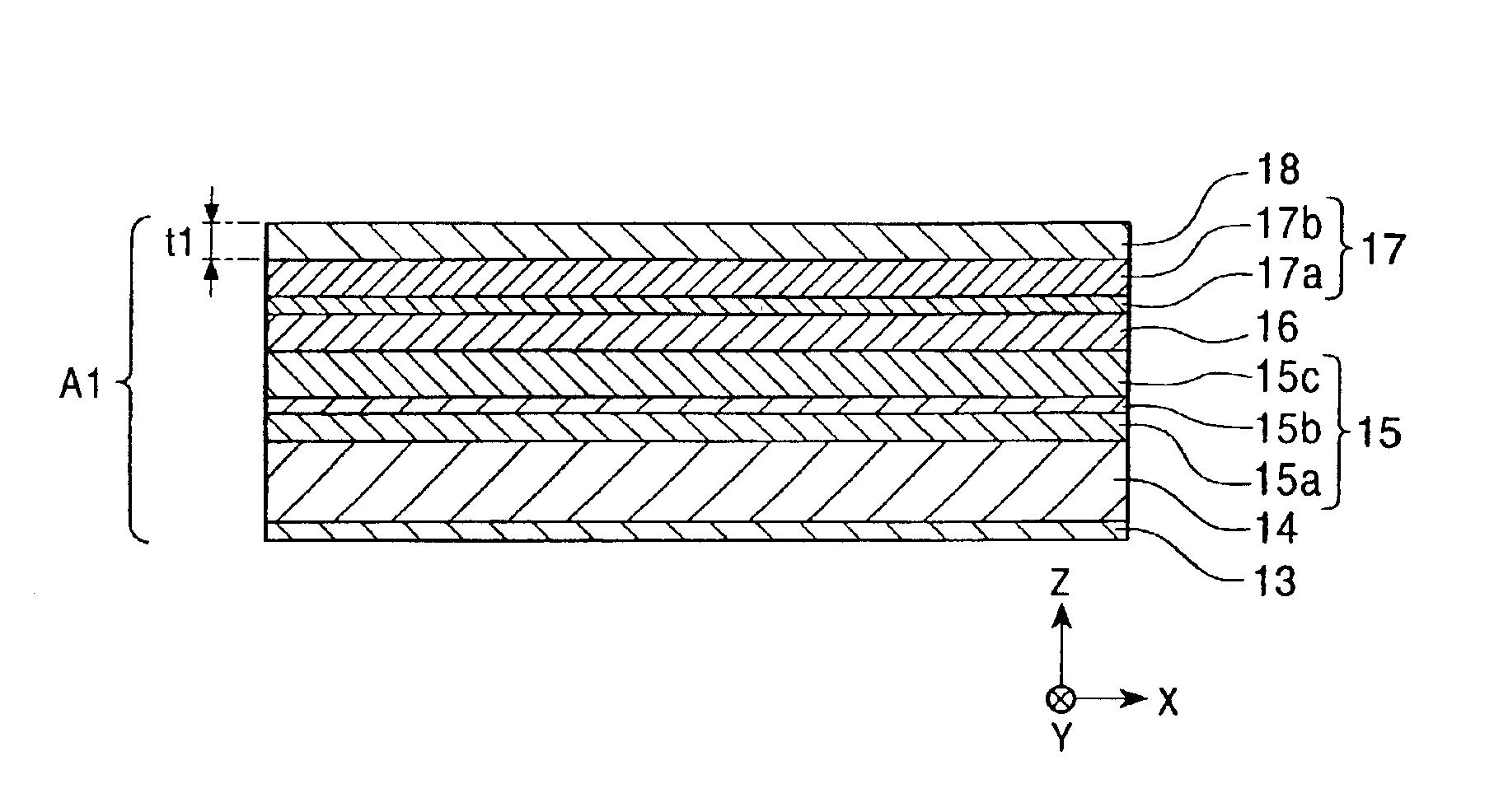
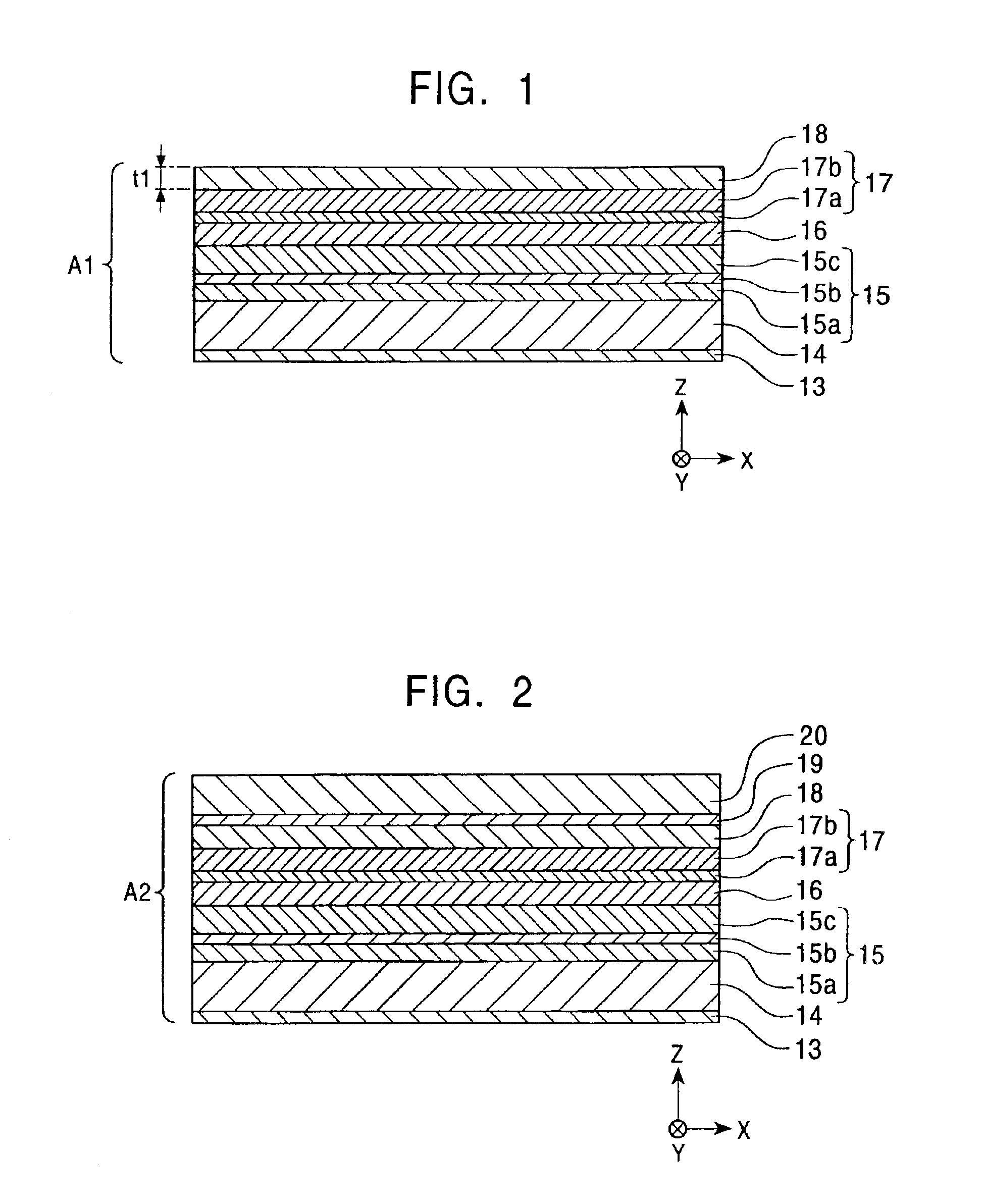
[0203]FIGS. 1-5 are diagrams that illustrate a method for manufacturing a magnetic sensing element according to a first embodiment of the present invention. FIGS. 1-5 are cross-sectional views of the magnetic sensing element in the course of manufacture, as viewed from the opposing face of the element.

[0204]If the magnetic sensing element is to be incorporated into a floating head, a lower shield layer is formed on a trailing end face of a ceramic slider with an insulating film, such as an Al2O3 film, therebetween.

[0205]In the step shown in FIG. 1, a first antiferromagnetic layer 14 is deposited on a base layer 13. A pinned magnetic layer 15 of a synthetic ferrimagnetic pinned type is then deposited on the first antiferromagnetic layer 14. The pinned magnetic layer 15 is constituted from a first pinned magnetic sublayer 15a, a nonmagnetic intermediate sublayer 15b, and a second pinned magnetic sublayer 15c. A nonmagnetic material layer 16, a free magnetic layer 17, and a nonmagnetic...

second embodiment

[0284]After the step shown in FIG. 4, the second antiferromagnetic layer 20 is milled partway using the electrode layers 21 as a mask to make a magnetic sensing element having an indent 30 as shown in FIG. 7. The indent 30 has a bottom portion 30b lying in the second antiferromagnetic layer 20 and having a track width Tw.

[0285]In the magnetic sensing element shown in FIG. 7, the bottom portion 30b of the indent 30 is located in the second antiferromagnetic layer 20. The free magnetic layer 17 and the ferromagnetic layer 19 are adjacent to each other with the nonmagnetic layer 18 therebetween. The magnetization directions of the free magnetic layer 17 and the ferromagnetic layer 19 are antiparallel to each other, i.e., in a ferrimagnetic state.

[0286]The free magnetic layer 17, the nonmagnetic layer 18, and the ferromagnetic layer 19 form a composite F. The composite F functions as one free magnetic layer of a synthetic ferrimagnetic type. This type of free magnetic layer has the same...

third embodiment

[0289]After the step shown in FIG. 4, the second antiferromagnetic layer 20 and the ferromagnetic layer 19 are milled using the electrode layers 21 as a mask to obtain a magnetic sensing element having an indent 31 as shown in FIG. 8. The indent 31 has side faces 31a penetrating the second antiferromagnetic layer 20. A bottom portion 31b of the indent 31 lies in the ferromagnetic layer 19 and has a width the same as the track width Tw.

[0290]In the magnetic sensing element shown in FIG. 8 also, the free magnetic layer 17, the nonmagnetic layer 18, and the ferromagnetic layer 19 form a composite F, and the composite F functions as one free magnetic layer of a synthetic ferrimagnetic type. In the present invention, no second antiferromagnetic layer 20 is provided above the sensitive region E of the free magnetic layer 17 in which the magnetization changes in response to an external magnetic field. As a result, the sensitivity of the sensitive region E to an external magnetic field can ...


PUM

PropertyMeasurementUnit
Timeaaaaaaaaaa
Timeaaaaaaaaaa
Timeaaaaaaaaaa

Abstract

A method for manufacturing magnetic sensing elements for use in magnetic sensors and hard disks. A ferromagnetic layer and a second antiferromagnetic layer are deposited on a nonmagnetic layer having a uniform thickness. The second antiferromagnetic layer is milled to form an indent. The resulting magnetic sensing element has a free magnetic layer reliably set in a single-magnetic-domain state in the track width direction.

Description

BACKGROUND OF THE INVENTION[0001]1. Field of the Invention[0002]The present invention relates generally to magnetic sensing elements for use in magnetic sensors and hard disks. In particular, the present invention relates to a method for manufacturing a magnetic sensing element having improved magnetic field sensitivity.[0003]2. Description of the Related Art[0004]FIG. 38 is a cross-sectional view of a magnetic sensing element made according to a known manufacturing method when viewed from a face of the element opposing a recording medium. This face is hereinafter referred to as the “opposing face”.[0005]The magnetic sensing element shown in FIG. 38 is of a spin-valve type which is a type of giant magnetoresistive (GMR) element utilizing the giant magnetoresistive effect. The spin-valve magnetic sensing element detects a recorded magnetic field on a recording medium such as a hard disk.[0006]As shown in FIG. 38, this spin-valve magnetic sensing element comprises: a composite 8 compr...

Claims


Application Information

Patent Timeline
IPC IPC(8): G01R33/06G01R33/09G11B5/39G11B5/31H01F10/16H01F10/32H01L43/08H01L43/12
CPCB82Y10/00B82Y25/00G01R33/093G11B5/3903G11B5/3116G11B5/3143Y10T29/49043G11B2005/3996Y10T29/49044Y10T29/49032Y10T29/49046
Inventor HASEGAWA, NAOYAUMETSU, EIJI
Owner TDK CORPARATION
Why Eureka
Try Eureka