
Oscillating hot wire of hot film flow sensor

a technology of hot film flow sensor and oscillating hot wire, which is applied in the direction of fluid speed measurement using thermal variables, instruments, measurement devices, etc., can solve the problems of sensor fragility, one problem was soon realized, and the floating element bulkiness of the floating element, etc., and achieve high spatial and temporal resolution

Inactive Publication Date: 2005-06-07
BOARD OF TRUSTEES OPERATING MICHIGAN STATE UNIV
View PDF2 Cites 28 Cited by
  • Summary
  • Abstract
  • Description
  • Claims
  • Application Information

AI Technical Summary

Benefits of technology

[0010]Accordingly, a feature of the present invention is to provide a high spatial and temporal resolution sensor for measurements of unsteady direction-reversing surface shear stress produced by a fluid flow in aerodynamic and hydrodynamic applications. Another feature of the present invention is to provide a sensor that can be used for flow velocity measurements in direction reversing flows.

Problems solved by technology

In addition to only indirectly measuring surface shear, the “hot” wire or “hot” film method does not measure directional changes of the flow.
Although capable of detecting direction and amount of surface shear, the bulkiness of their floating elements made them only useful for time-averaged measurements over a large area, rather than at a single point (never less than 1.0×1.0 mm2).
Although some success was achieved in constructing and testing the MEMS floating elements, one problem was soon realized.
This rendered these sensors fragile and, for all practical purposes, only useable by their makers under highly controlled conditions.
Additionally, the minute deflections of the floating element within the shuttle did not seem to produce sufficient signal-to-noise ratio, particularly when using capacitive pickups known in the art for detecting the deflection.
Unfortunately, there are several difficulties and limitations using this pulsed anemometry technology.
This limits sensor spatial resolution.
Again, this limits their application since they are impractical for applications involving array measurements.
Although this method overcomes some of the disadvantages of the time of flight technique, the frequency bandwidth remains limited to tens or a few hundred Hz due to separation of the thermal tuft sensors and their thermal inertia.

Method used


Image

  • Oscillating hot wire of hot film flow sensor
  • Oscillating hot wire of hot film flow sensor
  • Oscillating hot wire of hot film flow sensor

Examples


Embodiment Construction

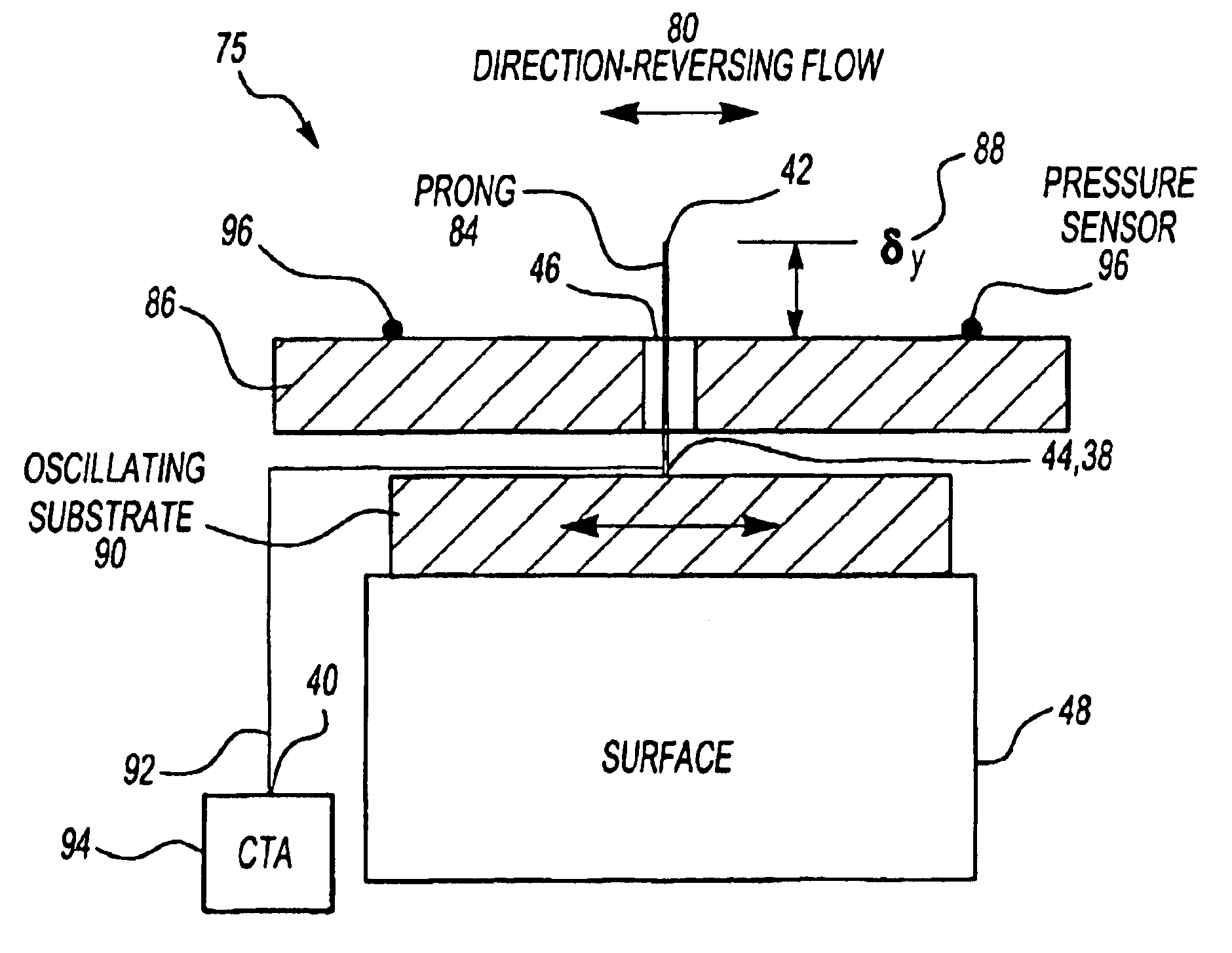
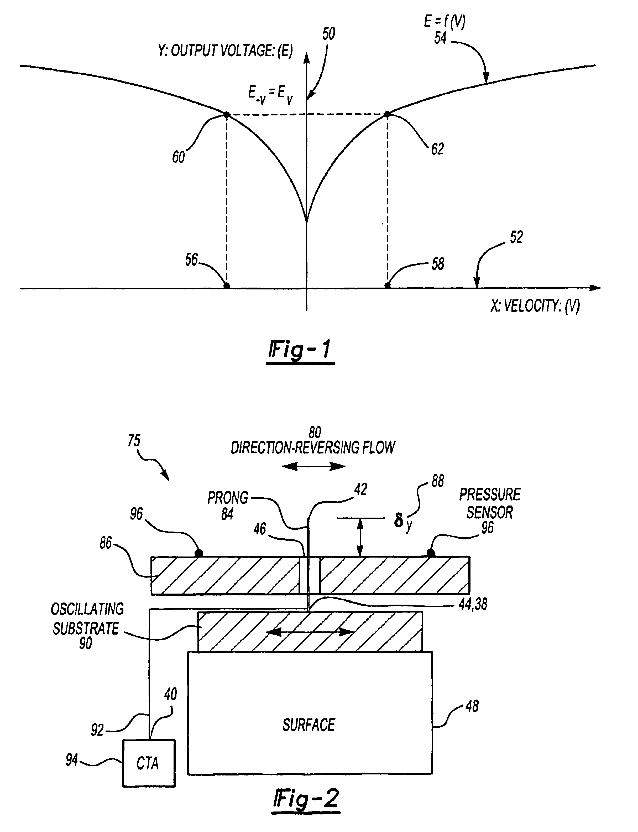
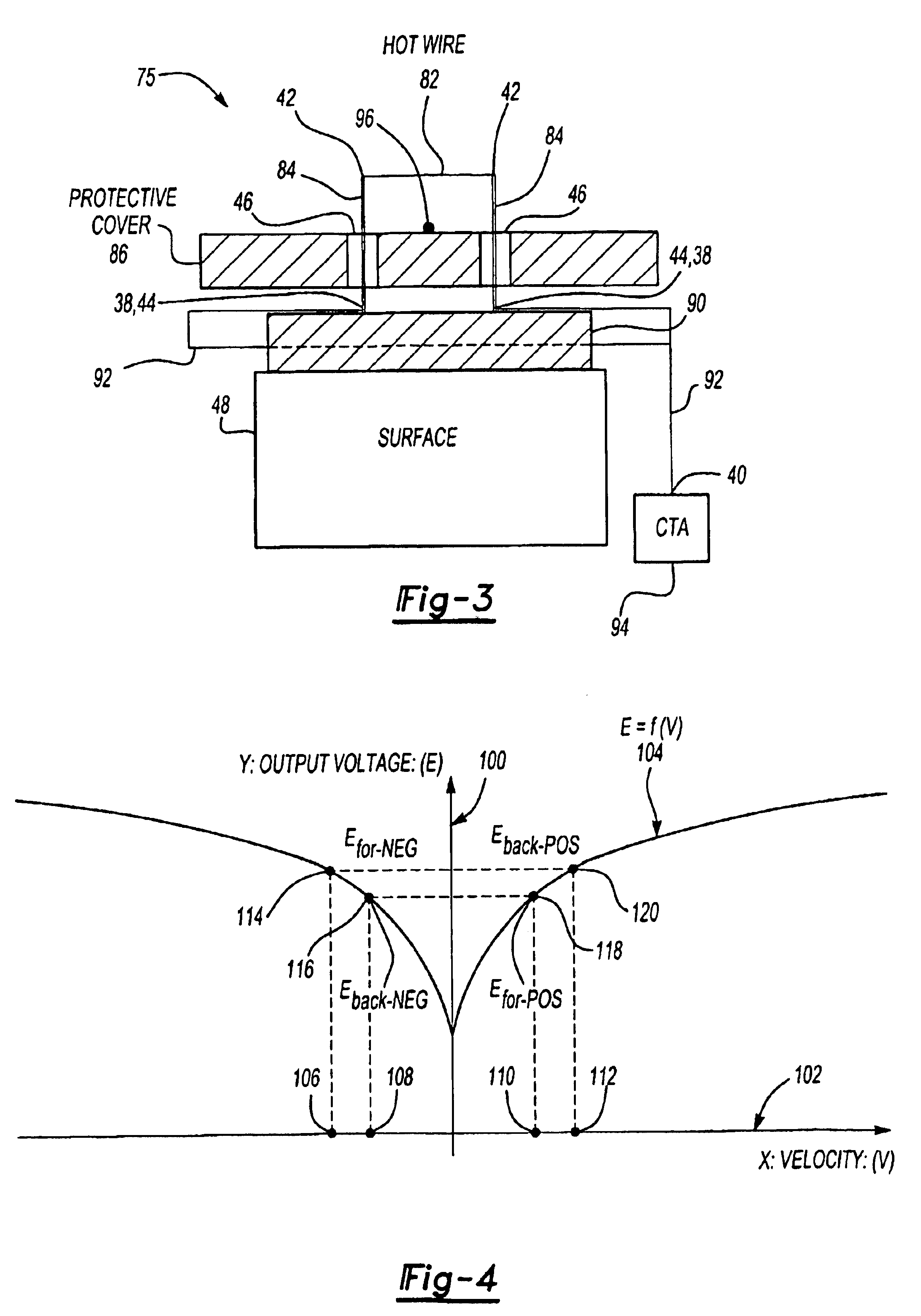
[0024]The present invention is a high spatial and temporal resolution sensor for measurements of unsteady direction-reversing surface (wall) shear stress produced by a fluid flow in aerodynamic and hydrodynamic applications. The flow measurement device of the present invention has high spatial (less than 1.0×1.0 mm2) and temporal resolution (greater than 500 Hz up to 100s kHz) to measure fluid flow properties in unsteady and direction-reversing fluid flows.

[0025]The surface shear sensor of the present invention measures fluid flow velocity (V) with a hot wire very close to the surface. If the wire is located within the region where the velocity varies linearly with distance from the wall, the surface shear stress (τw) can be estimated from the velocity measurement as:

τw=μdV / dy(y=0)≈μV / δy

where μ is the absolute viscosity, y is the direction normal to the wall, and δy is the distance from the wall to the hot wire. This technique, known in the art, measures shear stress in flows where ...


PUM


Abstract

This invention is a flow measurement device that has high spatial (less than 1.0×1.0 mm2) and temporal resolution (greater than 10 s to 100 s kHz) to measure flow properties in unsteady and direction-reversing conditions. The present invention can have an oscillating substrate, hot wire prongs, a hot wire attached to the hot wire prong, sensor leads from the prongs to a constant temperature anemometry circuit (CTA), means for the oscillating substrate to oscillate the substrate at a frequency greater than a characteristic cycle frequency of the flow to be measured, at a frequency less than a CTA bandwidth frequency, and such that a frequency and amplitude (Aw) of oscillation are sufficiently large to be detected, and means to obtain two measurements during an oscillation cycle when the hot wire is at its maximum oscillation velocity. Alternatively, the prongs can be eliminated and a hot wire or hot film can be directly applied to the oscillating substrate.

Description

CROSS-REFERENCE TO RELATED APPLICATION[0001]This application claims priority to a U.S. provisional patent application Ser. No. 60 / 340,649 titled, “Oscillating Hot-Wire or Hot-Film Flow Sensor,” filed 30 Oct. 2001. The entire disclosure of Ser. No. 60 / 340,649 is incorporated herein by reference in its entirety.FIELD OF INVENTION[0002]The present invention relates generally to flow measurement techniques, and specifically to an oscillating hot wire sensor for measurement of unsteady, direction-reversing flow velocity and wall-sheer stress in aerodynamic and hydrodynamic applications.BACKGROUND OF INVENTION[0003]A common method to indirectly measure unsteady surface shear uses a “hot” wire or “hot” film on the surface and is well known in the art. Surface shear is a tangential force exerted on a surface (wall) caused by flow moving over the surface. This method determines surface shear by measuring cooling of the wire or film at the surface and comparing it to known cooling velocity va...

Claims


Application Information

Patent Timeline
Patent Type & Authority Patents(United States)
IPC IPC(8): G01F1/68G01F1/684G01F1/688G01F1/692G01F1/696G01F1/698G01P5/12
CPCG01F1/68G01F1/684G01F1/688G01P5/12G01F1/696G01F1/698G01F1/692
Inventor NAGUIB, AHMED MOSTAFALI, YONGXIANG
Owner BOARD OF TRUSTEES OPERATING MICHIGAN STATE UNIV
Learn More