Stroboscopic optical image mapping system

a mapping system and optical image technology, applied in the field of optical systems, can solve the problems of optical image mapping system not being widely applied in the field of electrophysiology, the cost of the system is going to be high, and the drawbacks of conventional optical image mapping systems are still to be solved, so as to improve the follow-up image process and calculation, the effect of high spatial and temporal resolution

Inactive Publication Date: 2013-07-16
NAT TAIPEI UNIV OF TECH +1
View PDF2 Cites 0 Cited by
  • Summary
  • Abstract
  • Description
  • Claims
  • Application Information

AI Technical Summary

Benefits of technology

[0010]The present invention provides an optical image mapping system using stroboscopic and delay control for observing bio-transformation of an organic object in high spatial and temporal resolution, nondestructive, and contactless way without using an expansive image acquiring unit. In addition, the stroboscopic optical image mapping system has superior sensitivity for obtaining high-resolution fluorescent images, which improve the follow-up image process and calculation of the electrophysiologic analysis.

Problems solved by technology

Optical image mapping system is one of powerful tools for analyzing cardioelectrophysiology; however, conventional optical image mapping systems still have remaining drawbacks and need to be solved.
Despite of the merits described above, however, the conventional optical image mapping system requires image acquiring unit having high speed camera and massive image files storage media, so the cost of the system is going expensive.
Meanwhile, the limits of required inspection time and image resolution are also the causes that the optical image mapping system can't be commonly applied in the field of electrophysiology.

Method used


Image

  • Stroboscopic optical image mapping system
  • Stroboscopic optical image mapping system
  • Stroboscopic optical image mapping system

Examples


Embodiment Construction

[0029]For your esteemed members of reviewing committee to further understand and recognize the fulfilled functions and structural characteristics of the invention, several exemplary embodiments cooperating with detailed description are presented as the follows.

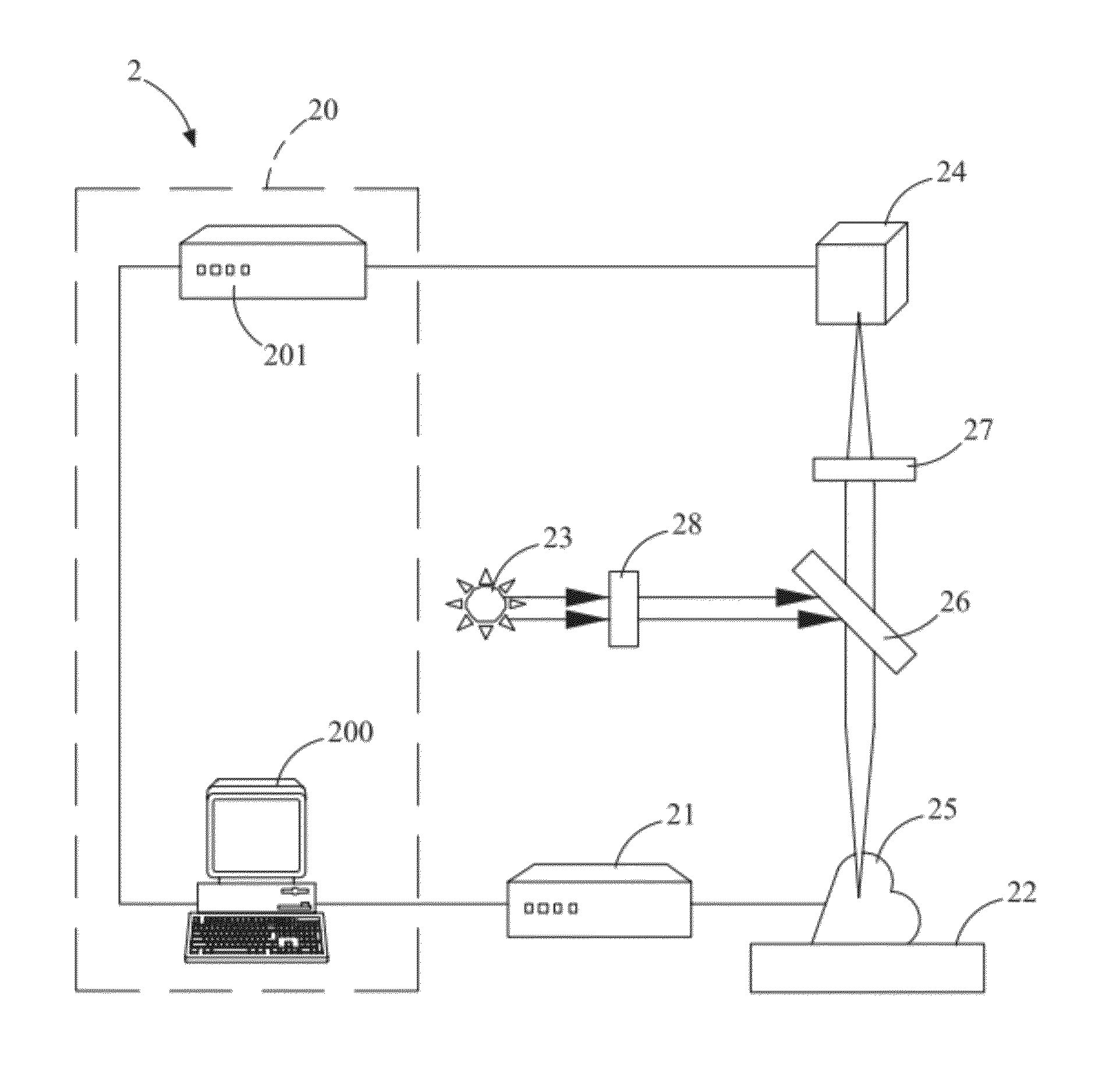
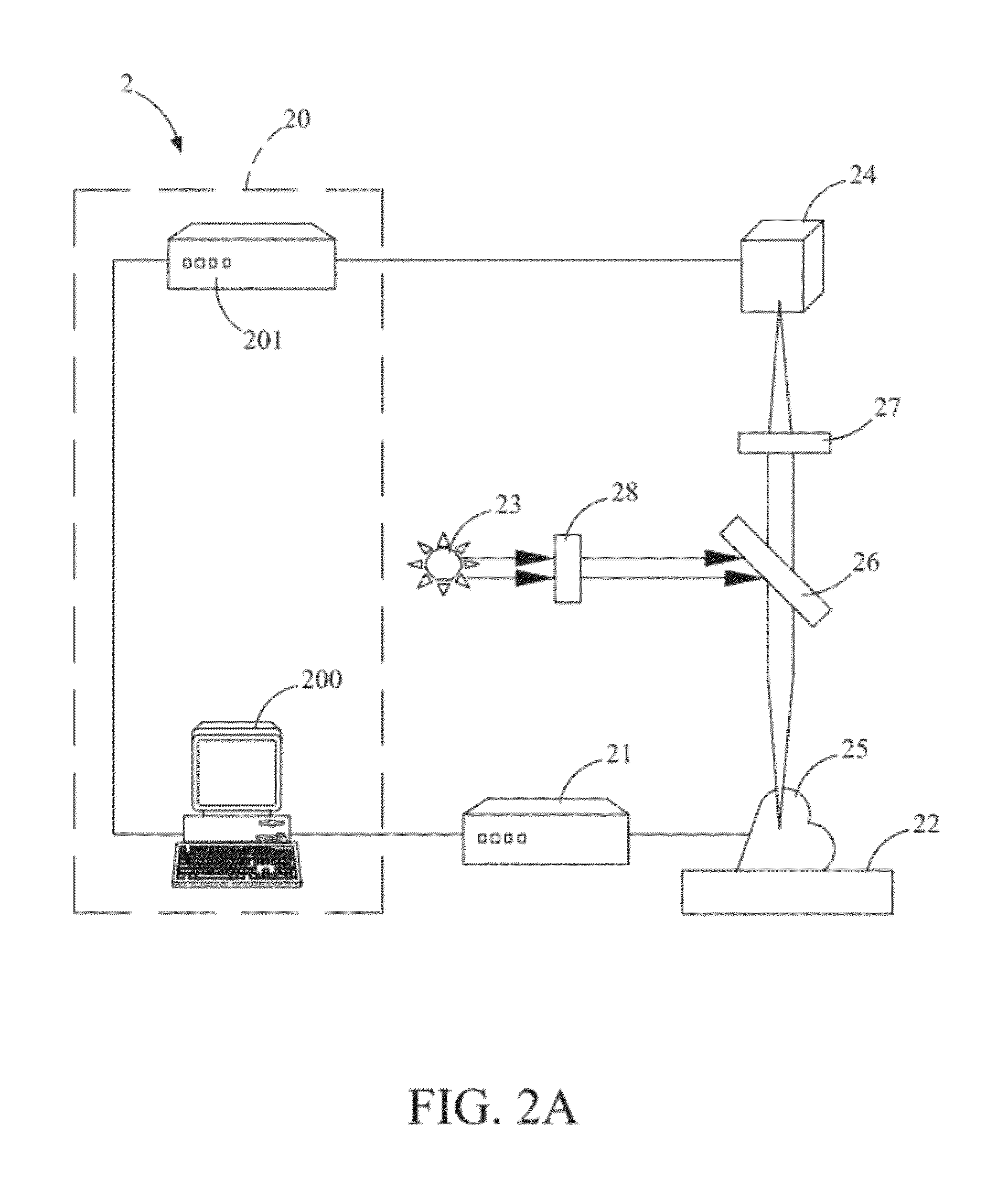
[0030]Please refer to FIG. 2A, which illustrates a first embodiment of the stroboscopic optical image mapping system according to the present invention. In the present embodiment, the stroboscopic optical image mapping system 2 comprises a control module 20, an electrical stimulator 21, a platform 22, a light source module 23, and an image acquiring unit 24. The control module 20 performs a delay control on a first pulse signal so as to form a delayed pulse signal. Please refer to FIG. 3A, which illustrates a first pulse signal according to the present invention. The first pulse signal 90 is composed of a plurality of pulses 900 formed by a pulse period T. Please refer to FIG. 3B, which illustrates a delayed pulse signal accor...


PUM

PropertyMeasurementUnit
wavelengthaaaaaaaaaa
stroboscopic optical image mappingaaaaaaaaaa

Abstract

The present invention provides a stroboscopic optical image mapping system comprising a control module, an optical module, and an image acquiring unit. The control unit forms a delayed pulse signal by modulating a first pulse signal having a plurality of pulses with a pulse period, wherein a time interval between two adjacent pulses of the delayed pulse signal has a time difference with respect to the pulse period. The optical module provides an incident light to be projected on an organic object, which has a dye therein and is stimulated by a second pulse signal for generating a sequential action potential. The fluorescence generates from the dye inside the organic object, which corresponds to the intensity of the sequential action potential. The image acquiring unit is actuated to acquire the fluorescent light according to the delayed pulse signal, thereby forming a plurality of fluorescent images.

Description

FIELD OF THE INVENTION[0001]The present invention relates an optical system, and more particularly, to a stroboscopic optical image mapping system.BACKGROUND OF THE INVENTION[0002]The organic object which includes excitable cells such as neurons or cardiomyocytes can generate action potentials. Under physiologic condition, cellular membrane potential is induced through ion permeability between the inner and the outer sides of the membrane in excitable cells. The excitable cells are responsible for cell-cell communication and triggering action potential.[0003]Electrophysiology is a study that investigates the electrical properties in living cells and tissues while cardioelectrophysiology is the study focusing on cardiomyocytes or cardiac tissues.[0004]Cardioelectrophysiology is a major index for studying the cardiac function and cardiac pathology. Optical image mapping system is one of powerful tools for analyzing cardioelectrophysiology; however, conventional optical image mapping s...

Claims


Application Information

Patent Timeline
Patent Type & Authority Patents(United States)
IPC IPC(8): G01J1/58G01N21/64
CPCG01N21/6456G01N21/6408
Inventor CHEN, LIANG-CHIALAI, YU-JUNZHANG, WAI-LUNYEH, HUNG-I
Owner NAT TAIPEI UNIV OF TECH
Why Eureka
Try Eureka