Device and method for measuring electrostrictive coefficients through linear frequency modulation multi-beam laser heterodyne

A linear frequency modulation and laser heterodyne technology, applied in the field of ultra-precision measurement, can solve the problems of low measurement accuracy, and achieve the effects of large measurement range, improved measurement accuracy and obvious experimental phenomena.

Inactive Publication Date: 2014-07-23
HEILONGJIANG UNIV
View PDF4 Cites 0 Cited by
  • Summary
  • Abstract
  • Description
  • Claims
  • Application Information

AI Technical Summary

Problems solved by technology

[0005] The purpose of the present invention is to solve the problem of low measurement accuracy of the existing method for measuring the electrostrictio

Method used


Image

  • Device and method for measuring electrostrictive coefficients through linear frequency modulation multi-beam laser heterodyne
  • Device and method for measuring electrostrictive coefficients through linear frequency modulation multi-beam laser heterodyne
  • Device and method for measuring electrostrictive coefficients through linear frequency modulation multi-beam laser heterodyne

Examples


specific Embodiment approach 1

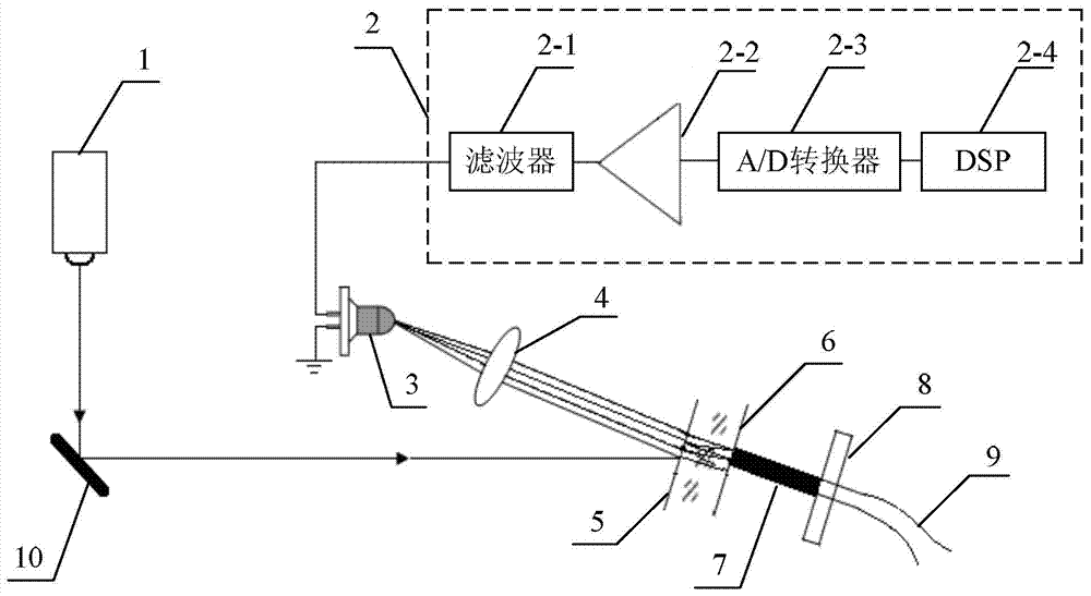
[0023] Specific implementation mode one: combine figure 1 Describe this embodiment, the device for chirp multi-beam laser heterodyne measurement of electrostriction coefficient described in this embodiment includes a chirp laser 1, a photodetector 3, a converging lens 4, a thin glass plate 5, and a No. 2 plane mirror 6 and adjustment frame 8;

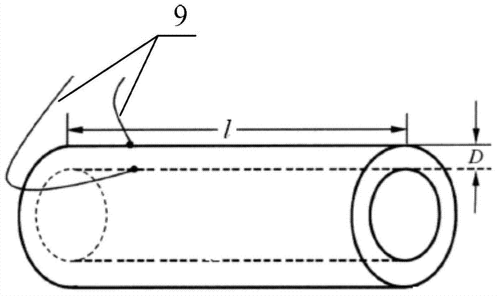
[0024] The adjustment frame 8 is used to fix the piezoelectric body 7 to be tested, and the No. 2 plane reflector 6 is used to be fixed on an end face of the piezoelectric body 7 to be tested. The glass plate 5 is arranged parallel to the No. 2 plane reflector 6;

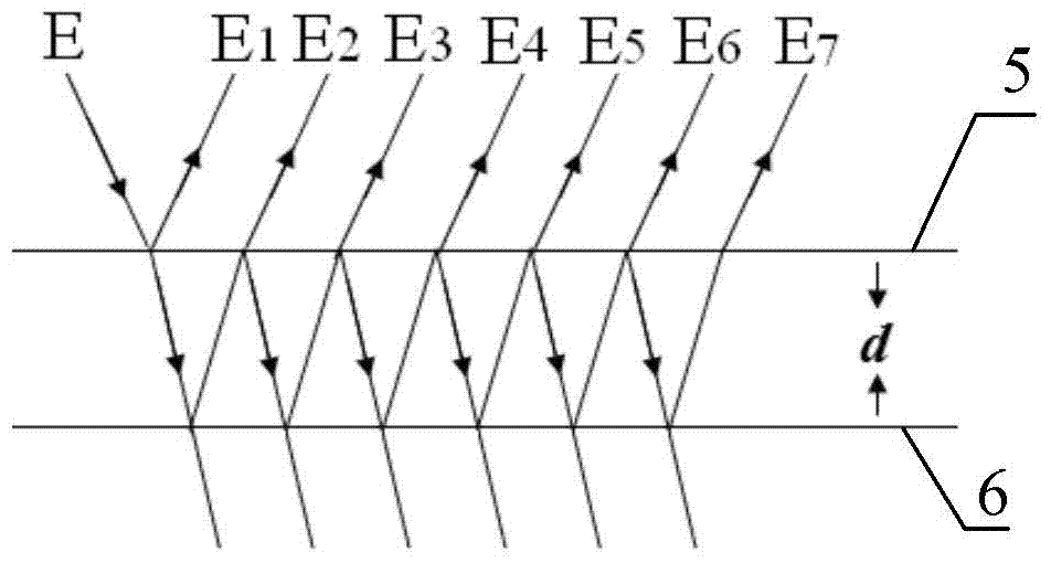
[0025] The laser light emitted by the chirp laser 1 is incident on the surface of the thin glass plate 5, and the laser light transmitted through the thin glass plate 5 is incident on the second plane reflector 6, and between the second plane reflector 6 and the thin glass plate 5 Multiple reflected light beams are obtained after multiple reflections, and the multiple refle...

specific Embodiment approach 2

[0029] Specific implementation mode two: combination figure 1 Describe this embodiment. This embodiment is a further limitation of the device for measuring the electrostrictive coefficient by chirp multi-beam laser heterodyne described in Embodiment 1. In this embodiment, the chirp multi-beam laser heterodyne measurement The device of the electrostriction coefficient also includes a signal processing system 2, the detection signal input end of the signal processing system 2 is connected to the detection signal output end of the photodetector 3, and the signal processing system 2 includes a filter 2-1, a front Amplifier 2-2, A / D converter 2-3 and DSP2-4, the signal input end of the filter 2-1 is the detection signal input end of the signal processing system 2, the filter 2-1 The signal output terminal is connected to the signal input terminal of the preamplifier 2-2, and the signal output terminal of the preamplifier 2-2 is connected to the analog signal input terminal of the A...

specific Embodiment approach 3

[0031] Specific implementation mode three: combination figure 1 Describe this embodiment. This embodiment is a further limitation of the device for measuring the electrostrictive coefficient by chirp multi-beam laser heterodyne described in Embodiment 1. In this embodiment, the chirp multi-beam laser heterodyne measurement The electrostrictive coefficient device also includes a No. 1 plane reflector 10 , and the laser light emitted by the chirp laser 1 is reflected by the No. 1 plane reflector 10 and then incident on the surface of the thin glass plate 5 .

[0032] In this embodiment, a No. 1 plane reflector 10 is arranged between the chirp laser 1 and the thin glass plate 5. The No. 1 plane reflector 10 reflects the laser light emitted by the chirp laser 1, and the reflected light is incident on the thin glass plate. 5 surfaces. During measurement, the incident angle of the laser light on the thin glass plate 5 can be adjusted by adjusting the angle of the No. 1 flat mirror ...


PUM

PropertyMeasurementUnit
Thicknessaaaaaaaaaa

Abstract

The invention discloses a device and a method for measuring electrostrictive coefficients through linear frequency modulation multi-beam laser heterodyne and relates to the field of ultra-precise measurement. The device and the method for measuring the electrostrictive coefficients through the linear frequency modulation multi-beam laser heterodyne aim at solving the problem that the existing electrostrictive coefficient measuring method is low in measuring accuracy. An adjusting frame is used for fixing piezo-electric crystal with voltage to be measured; a second planar reflecting mirror is used for being fixed on one end surface of the piezo-electric crystal with the voltage to be measured; a thin glass plate and the second planar reflecting mirror are arranged in a parallel mode; laser sent out from a linear frequency modulation laser enters into the surface of the thin glass plate, the laser enters into the second planar reflecting mirror after being transmitted through the thin glass plate, and the laser is focused on the photosensitive surface of a photoelectric detector after being reflected through the thin glass plate. According to the device and the method for measuring the electrostrictive coefficients through the linear frequency modulation multi-beam laser heterodyne, the length variation amount of the piezo-electric crystal with the voltage to be measured is modulated within the frequency difference of intermediate frequency heterodyne signals, the length variation amount of a plurality of piezo-electric crystal with the voltage to be measured are obtained simultaneously due to measurement of the frequency difference, and the measuring error is 0.04 %. The device and the method for measuring the electrostrictive coefficients through the linear frequency modulation multi-beam laser heterodyne is applicable to ultra-precise measuring and detecting, device machining, laser radar system and the like.

Description

technical field [0001] The invention relates to the field of ultra-precision measurement. Background technique [0002] In all electromechanical systems and devices involved in automatic control, the driver is often considered to be one of the most critical factors limiting its performance and life. Among the many types of drivers, piezoelectric / electrostrictive drivers are due to their fast response, It has attracted much attention because of its high bearing capacity, low energy consumption and low price. At present, piezoelectric / electrostrictive drivers have been successfully applied in many technical fields such as laser resonator, precision positioning, precision machining, intelligent structure, bioengineering, aerospace, electronic communication, automobile industry, robot joints, medical equipment, etc., and An industry with great potential is being formed. Therefore, the development and application of piezoelectric / electrostrictive new materials, new processes an...

Claims


Application Information

Patent Timeline
IPC IPC(8): G01B11/16
Inventor 李彦超杨九如冉玲苓高扬柳春郁杜军丁群王春晖马立峰于伟波
Owner HEILONGJIANG UNIV
Why Eureka
Try Eureka