Two-piece valve stem seal

a valve stem and sealing body technology, applied in the direction of engine starters, muscle operated starters, machines/engines, etc., can solve the problems of unfavorable product life, unfavorable product quality, and unfavorable product quality, so as to improve product quality and product life, reduce the wear of the seal lip of the sealing body, and facilitate the sealing installation and removal

Active Publication Date: 2005-06-07
FREUDENBERG NOK GEN PARTNERSHIP
View PDF6 Cites 32 Cited by
  • Summary
  • Abstract
  • Description
  • Claims
  • Application Information

AI Technical Summary

Benefits of technology

[0012]Preferably, the improved two-piece valve stem seal includes rigid cylindrical shells, preferably composed of a metal or metal-containing material. The resilient sealing body can be composed of rubber or other resilient elastomers and is preferably bonded directly to the preferred metal casing of the first cylindrical shell. This allows the sealing body in many embodiments to remain stationary with the first cylindrical shell thus reducing wear of the sealing body's seal lip and extending product life. Such bonded resilient seal body also allows for easier seal installation and removal, greater support of the sealing body's sealing lip and superior control of oil metering for lubrication of the valve stem.

Problems solved by technology

If the rigid shell is not properly located in relation to the valve guide, the sealing element might not properly seat upon the valve stem thus causing non-uniform pressures at the cylinder and valve guide, undesirable wear patterns on the seal or valve stem and unpredictable lubrication of the valve stem and valve guide.
Some prior art valve stem seals have had histories of cracked flanges during vehicle operations due to shock waves and internal stresses at the flange portion of the valve stem seal.
Some of such prior art valve stem seals also have not had sufficiently flat flange portions, thus further increasing the likelihood of flange cracking.
In addition some prior art two-piece valve stem seal assemblies have been difficult to assemble by their manufacturers, as well as presenting further difficulties to consequent manufacturers assembling the finished valve stem seal assembly into an engine or other device using such assemblies.
These problems sometimes have resulted from the need to assemble or insert the “upper” generally cylindrical shell portion of the valve stem seal assembly “upwardly” into the “lower” generally cylindrical shell portion from the “bottom” of the lower shell portion, i.e., from the end of the lower shell portion that bears against the engine's cylinder head or other such member of a device through which the valve stem extends.
This difficulty sometimes results from the “upper”, end portion of the lower shell portion having a relatively small bearing surface (against which the insertion forces are directed) when compared to the bearing surface at the lower end of the lower shell portion.
This of course can cause malfunction, or at least temporarily halt or slow down, such consequent assembly operations.

Method used


Image

  • Two-piece valve stem seal
  • Two-piece valve stem seal
  • Two-piece valve stem seal

Examples


Embodiment Construction

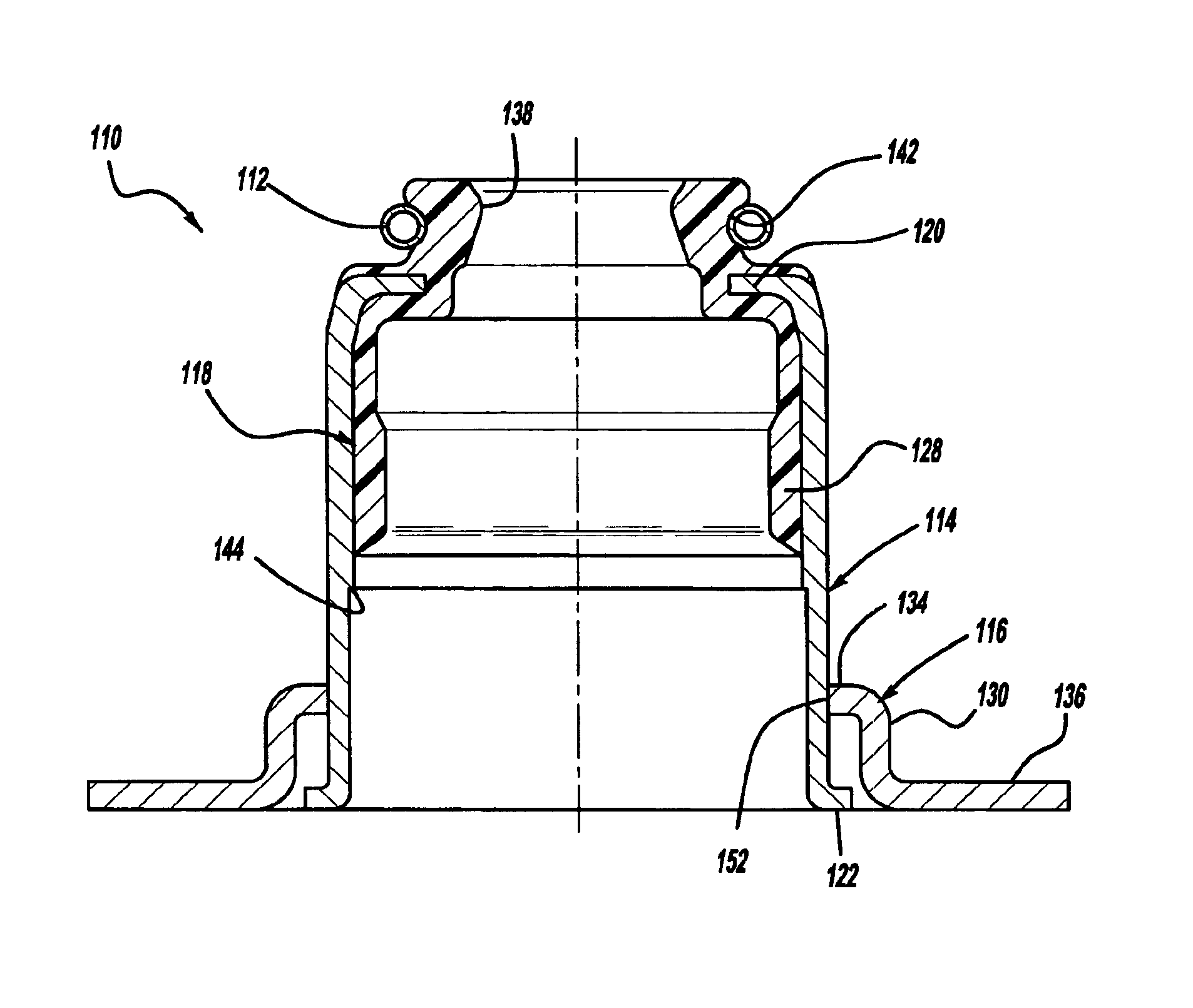
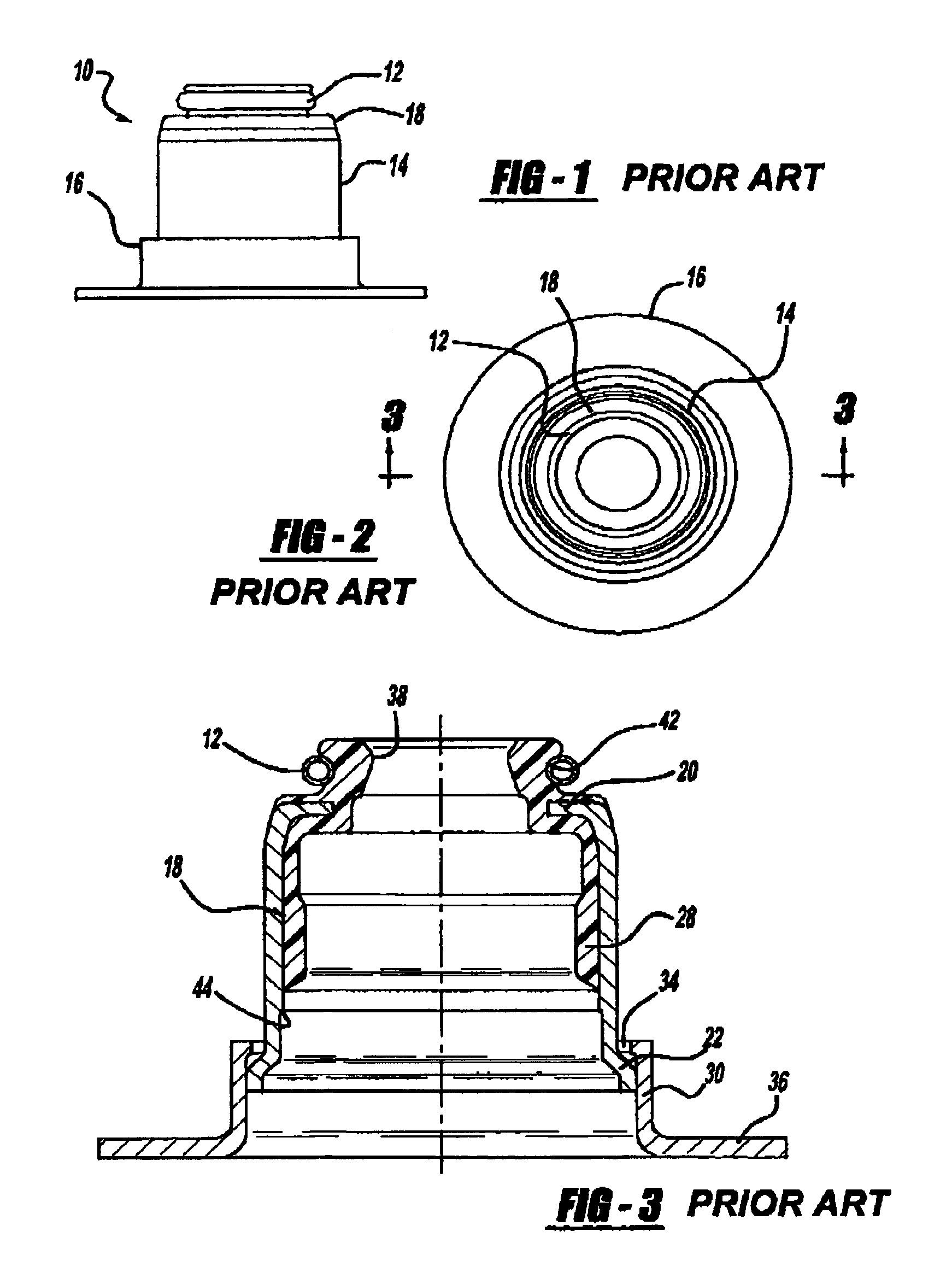
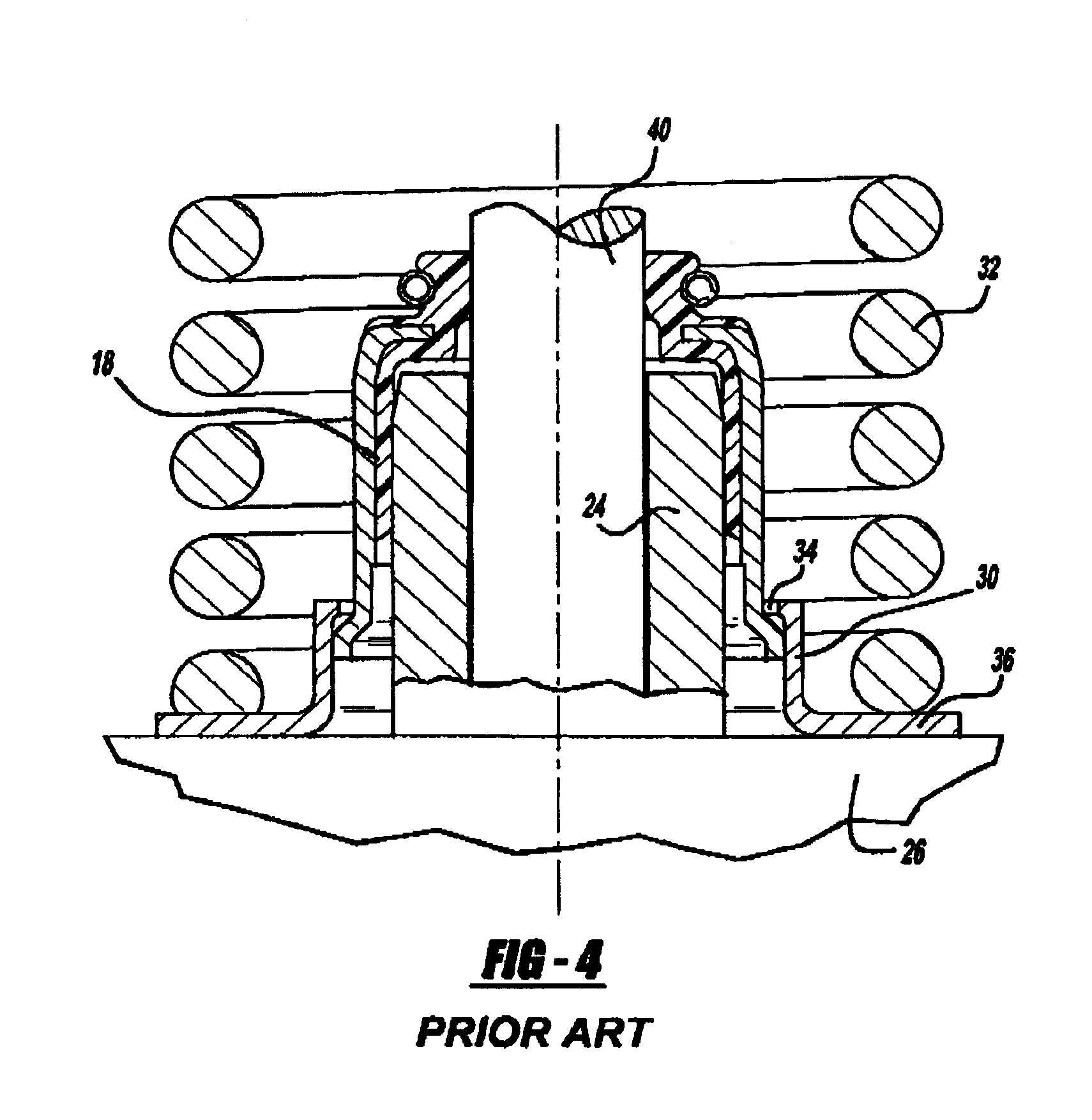
[0020]FIGS. 1 through 12 illustrate various embodiments of a two-piece valve stem seal assembly according to U.S. Pat. No. 5,775,284 and according to the present invention. For purposes of example only, FIGS. 1 through 12 are primarily directed toward an internal combustion engine application. It should be noted, however, as will become apparent to those skilled in the art from the following description and claims, the principles of the present invention are equally applicable to other devices having valves with valve stems thereon.

[0021]Referring initially to FIGS. 1 through 4, a two-piece valve stem seal assembly 10 preferably has a two-piece construction, including a first generally rigid cylindrical shell 14, preferably made of a metal-containing material, but which may be made of ceramic or other relatively hard and rigid materials. Although the first shell 14 is preferably generally hollow and cylindrical in shape, other shapes may be used depending on the needs of the specifi...


PUM


Abstract

A two piece valve stem seal assembly including first and second generally cylindrical shells, one of which is partially axially nested or inserted within the other. The valve stem seal assembly also includes an engagement portion on the one of the shells for grippingly engaging the outer shell in order to substantially prevent or at least minimize the possibility of axial separation of the shells during subsequent assembly into an engine or other valve-containing device. The assembly may also optionally include a discontinuity on the one of the shells for axially retaining or axially interlocking the shells in order to substantially prevent or at least minimize such possibility of axial separation.

Description

BACKGROUND OF THE INVENTION[0001]The present invention relates to valve stem seals, and more particularly to a two-piece valve stem seal preferably for use in an internal combustion engine, but applicable to other valve stem sealing applications.[0002]The primary function of a valve stem seal in an internal combustion engine, for example, is to allow adequate lubrication at the valve stem / valve guide interface while minimizing internal oil consumption. Valve stem seals of this general type are known in the prior art, as shown in U.S. Pat. Nos. 5,558,056; 4,947,811; 4,909,202; 3,554,562; and 3,554,180, for example. In addition, a two-piece valve stem seal of this general type is shown in U.S. Pat. No. 5,775,284, which is assigned to the same assignee as the present application and which has overlapping inventorship with the present invention.[0003]A valve stem seal assembly generally includes a rigid shell structure and a seal body, with the assembly having a generally hollow interio...

Claims


Application Information

Patent Timeline
Patent Type & Authority Patents(United States)
IPC IPC(8): F01L3/00F01L3/08F16K41/08F16K41/00F16J15/32
CPCF01L3/08F16K41/08F01L2101/02F01L2101/00F01L2301/00F01L2301/02A47G25/56A47G25/58
Inventor BUTCHER, TIGREE MILAMGRISWOLD, MILTON LOMAN
Owner FREUDENBERG NOK GEN PARTNERSHIP
Why Eureka
Try Eureka