
Contaminant-resistant pivot joint for outdoor lighting fixture

a technology for outdoor lighting and pivot joints, which is applied in the field of outdoor lighting, can solve the problems of easy breakage, weakest point of fixtures, and fixtures that are subject to impact from gardening tools and equipment, and achieve the effect of reducing the space within which contaminants can accumula

Inactive Publication Date: 2005-06-07
HUNTER INDUSTRIES
View PDF5 Cites 50 Cited by
  • Summary
  • Abstract
  • Description
  • Claims
  • Application Information

AI Technical Summary

Benefits of technology

[0008]It is an advantage of the present invention to provide a pivot joint for use in an outdoor lighting system that minimizes the space within which contaminants can collect.

Problems solved by technology

While the pivoting joints provide significant adaptability in the aiming of the light, they constitute the weakest point in the fixture.
The fixtures are subject to impact from gardening tools and equipment as well as persons inadvertently running into or kicking the fixture.
Exposure to various environmental conditions including temperature extremes, moisture and corrosive fertilizers and insecticides can weaken the joints and cause them to be easily broken.
A significant disadvantage of this particular configuration is that when the fixture is exposed to the elements, the toothed notches become fouled by dirt and corrosion and the two parts of the joint can no longer remain engaged.
Furthermore, the adjustment is incremental, limited by the sizes and number of notches.

Method used


Image

  • Contaminant-resistant pivot joint for outdoor lighting fixture
  • Contaminant-resistant pivot joint for outdoor lighting fixture
  • Contaminant-resistant pivot joint for outdoor lighting fixture

Examples


Embodiment Construction

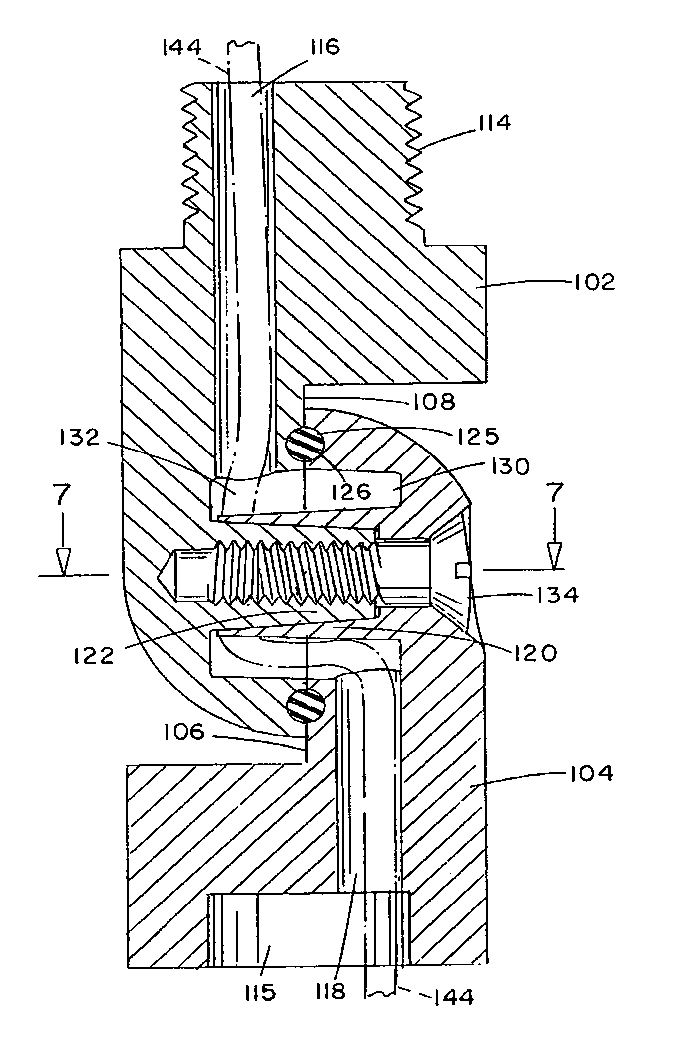
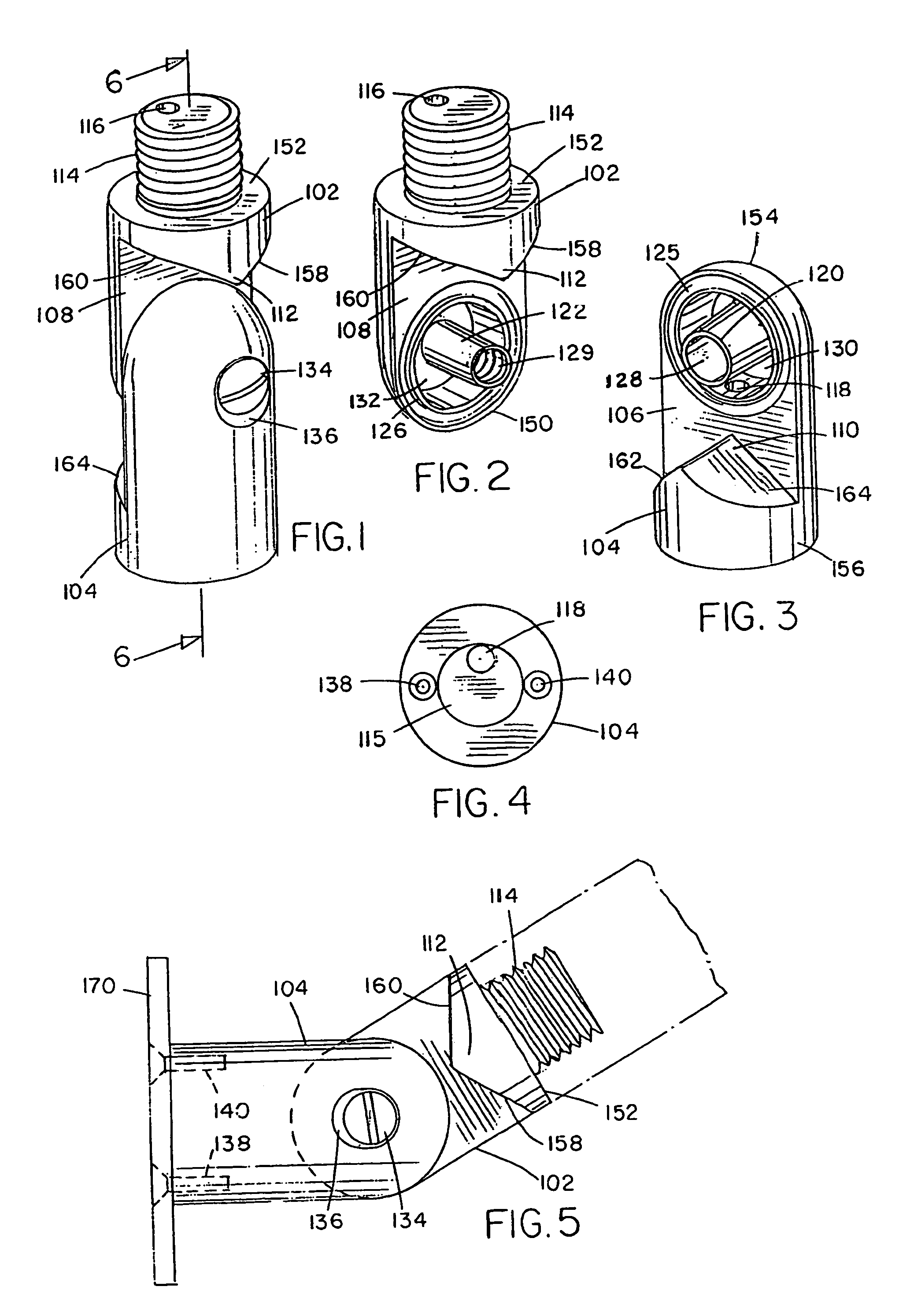
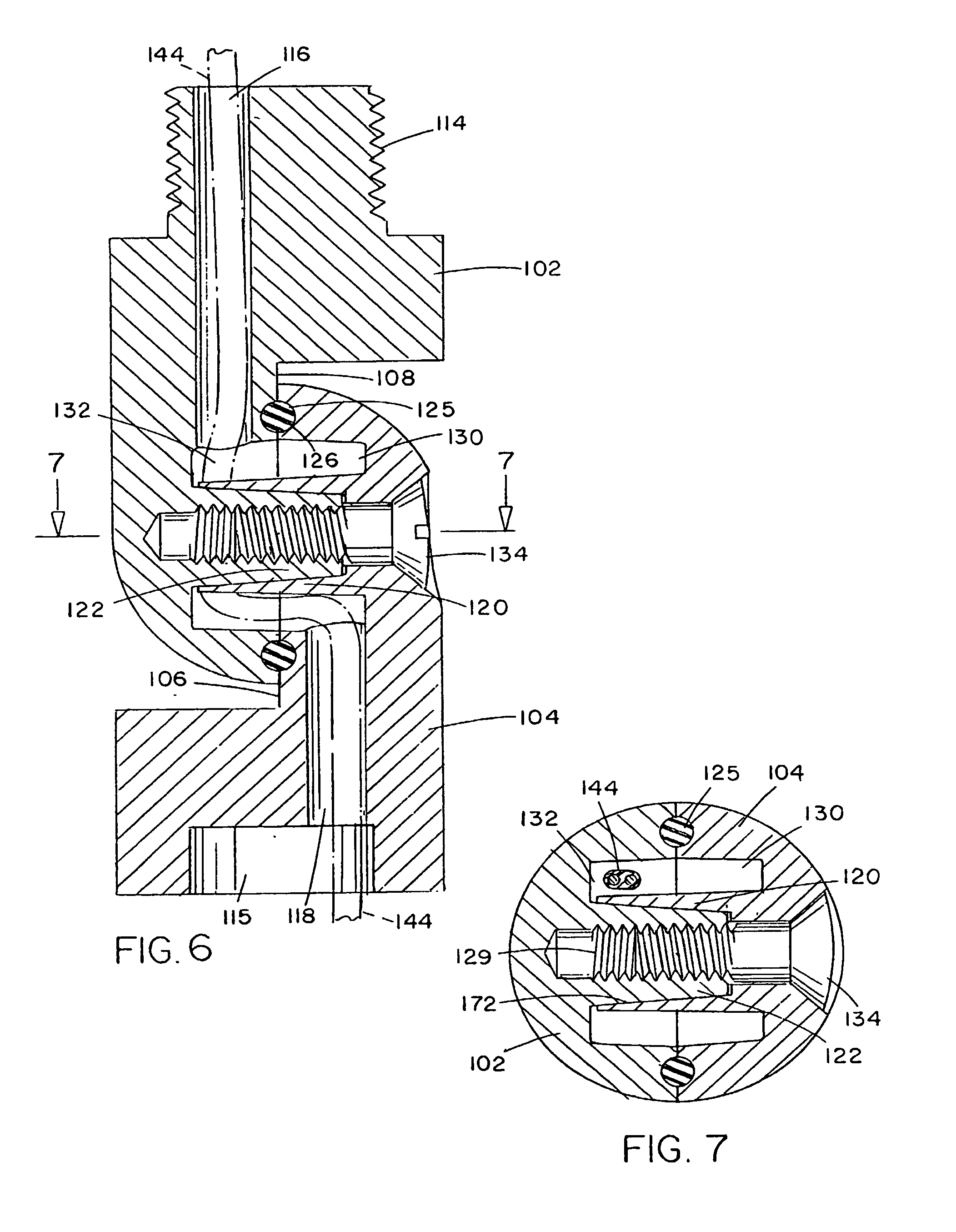
[0019]Referring to FIG. 1, the knuckle joint assembly is formed by the combination of base knuckle 102, top knuckle 104, and locking screw 134. Base knuckle 102 has a proximal end 150 corresponding to the pivot point and a distal end 152 which provides means for attaching to a support or other like structure such as a spike which may be driven into the ground, a pole or wall mount (not shown). A conduit for passing electrical wiring from a voltage supply to a lamp extends through the joint assembly, beginning at bore 116 at distal end 152 and exiting through the distal end 156 of top knuckle 102. In the preferred embodiment, base knuckle 102 and top knuckle 104 are formed from brass by CNC machining of a cylindrical bar, or by other machining or forming techniques known in the art. Other corrosion resistant materials may be used as well, including stainless steel, aluminum, copper, ceramic, or high temperature plastics or composites, by machining, die casting or molding where approp...


PUM


Abstract

The pivoting knuckle joint for an outdoor lighting fixture comprises a base knuckle, a top knuckle and a fastener for locking the base and top knuckles in position. Each of the base knuckle and top knuckle has a generally cylindrical body with a domed top, a portion of which is cut-away to form a flattened face, and circular cavity formed in the flattened face with a tapered ferrule formed in and extending from the cavity. The ferrule of one of the knuckles has a smaller diameter than the other, so that the smaller ferrule fits within the larger ferrule, forming a pivot point. The relative diameters are adapted to closely fit such that friction is generated between the interfitting ferrules to form a taper lock, resisting rotation of one knuckle relative to the other. In the preferred embodiment, the smaller ferrule has an internal thread formed therein for receiving a locking screw inserted through the body of the knuckle with the larger ferrule, permitting the position of the joint to be locked in place after adjustment. Bores are formed through the base and top knuckles to provide a conduit for an electrical wire to pass through the assembly.

Description

RELATED APPLICATIONS[0001]This is a continuation of application Ser. No. 09 / 536,676, filed Mar. 28, 2000, now abandoned.FIELD OF THE INVENTION[0002]Environmental lighting, particularly outdoor lighting, is well known in commercial or public settings, such as parks and schools. Such lighting has also become increasingly popular for use in private residences, both to enhance the appearance and safety of the outdoor area and for security by eliminating hiding place and unobserved entry points for intruders.[0003]Landscape and outdoor lighting systems generally include one or more lighting fixtures which are connected to either a 12 V transformer or a standard 120 VAC line. The lighting fixtures generally include a housing, a reflector assembly having a halogen or conventional bulb, and a lens or window. Many configurations are known, each of which provides a different lighting effect.[0004]One of the more popular and versatile lighting fixtures utilizes a cylindrical housing attached t...

Claims


Application Information

Patent Timeline
IPC IPC(8): F16L27/00F21V19/02F16C11/04F16M11/06F21V21/26F21V27/00
CPCF16C11/04F16M11/06F16M13/02F21V21/26Y02B20/72F21V27/00F21W2131/10
Inventor BEADLE, JOSHUA
Owner HUNTER INDUSTRIES
Learn More