Interior rearview mirror system including a pendent accessory
- Summary
- Abstract
- Description
- Claims
- Application Information
AI Technical Summary
Benefits of technology
Problems solved by technology
Method used
Image
Examples
first embodiment
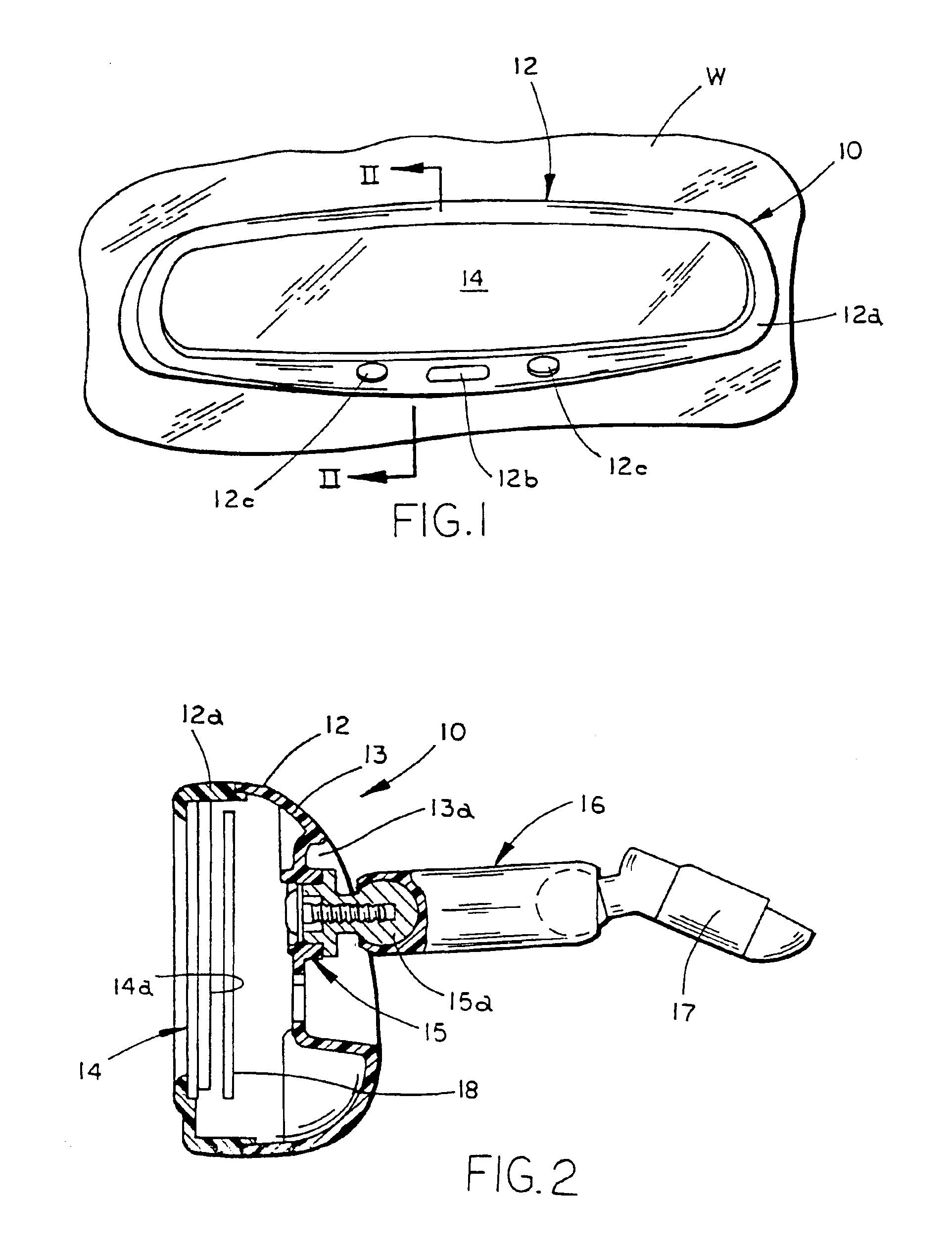
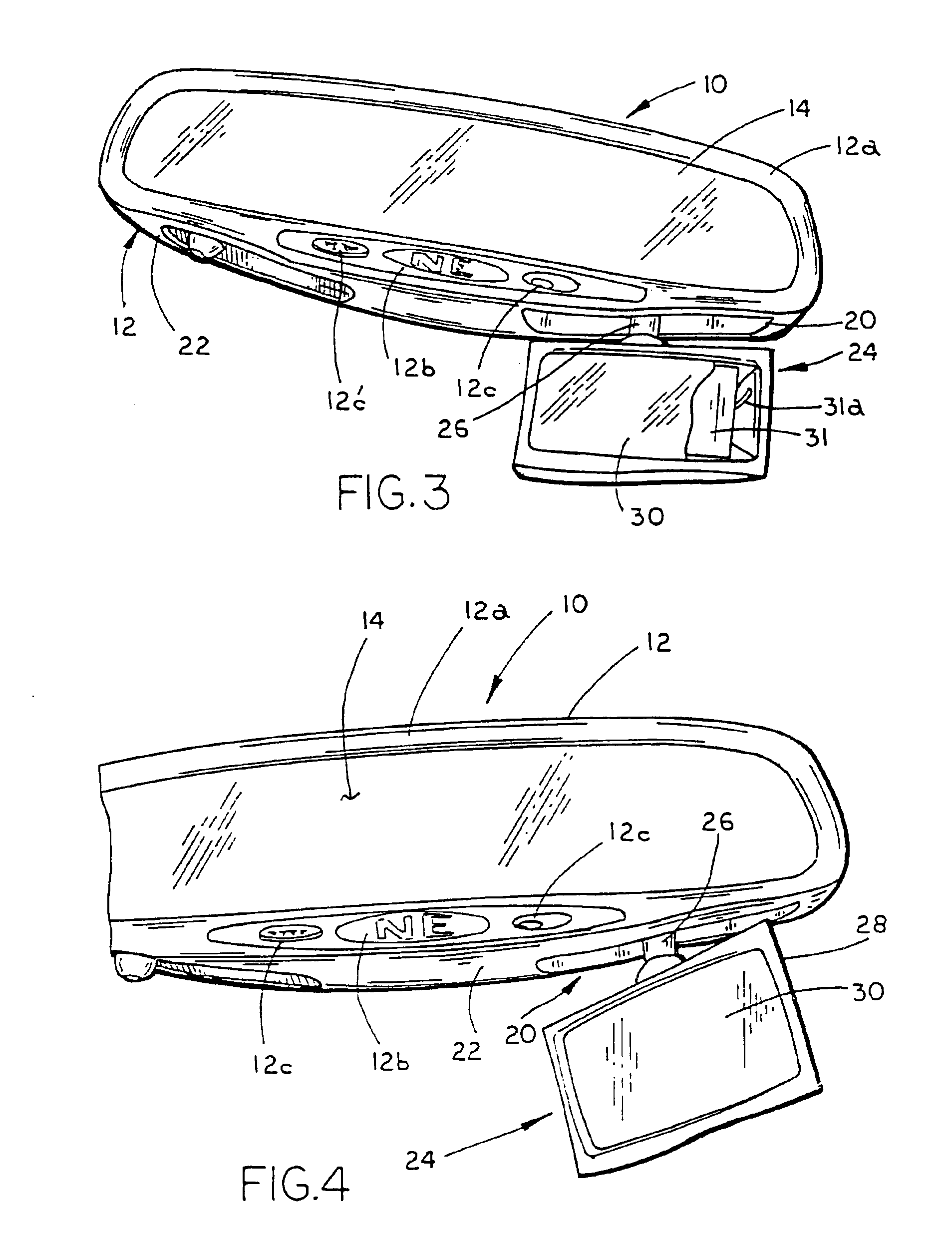
[0084]Referring to FIG. 1, the numeral 10 generally designates the interior rearview mirror assembly of the present invention. Assembly 10 is adapted to be releasably secured or coupled to the front windshield W of a vehicle in a conventional manner. Alternatively, assembly 10 can be adapted to secure or couple to the header portion of the vehicle above the windshield, as is known in the art. Assembly 10 includes a mirror casing or housing 12 and a reflective element 14 which is supported in or on casing 12 in a conventional manner. Referring to FIG. 2, in the illustrated embodiment, mirror assembly 10 is mounted to windshield W by a support arm 16 and a break-away mounting bracket or mirror mount 17 which releasably mounts to a conventional mirror button on windshield W. Preferably support arm 16 is a conventional double ball type support arm which permits multi axis positioning of casing 12 about bracket 17. It should be understood that any suitable type of support arm may be empl...
fourth embodiment
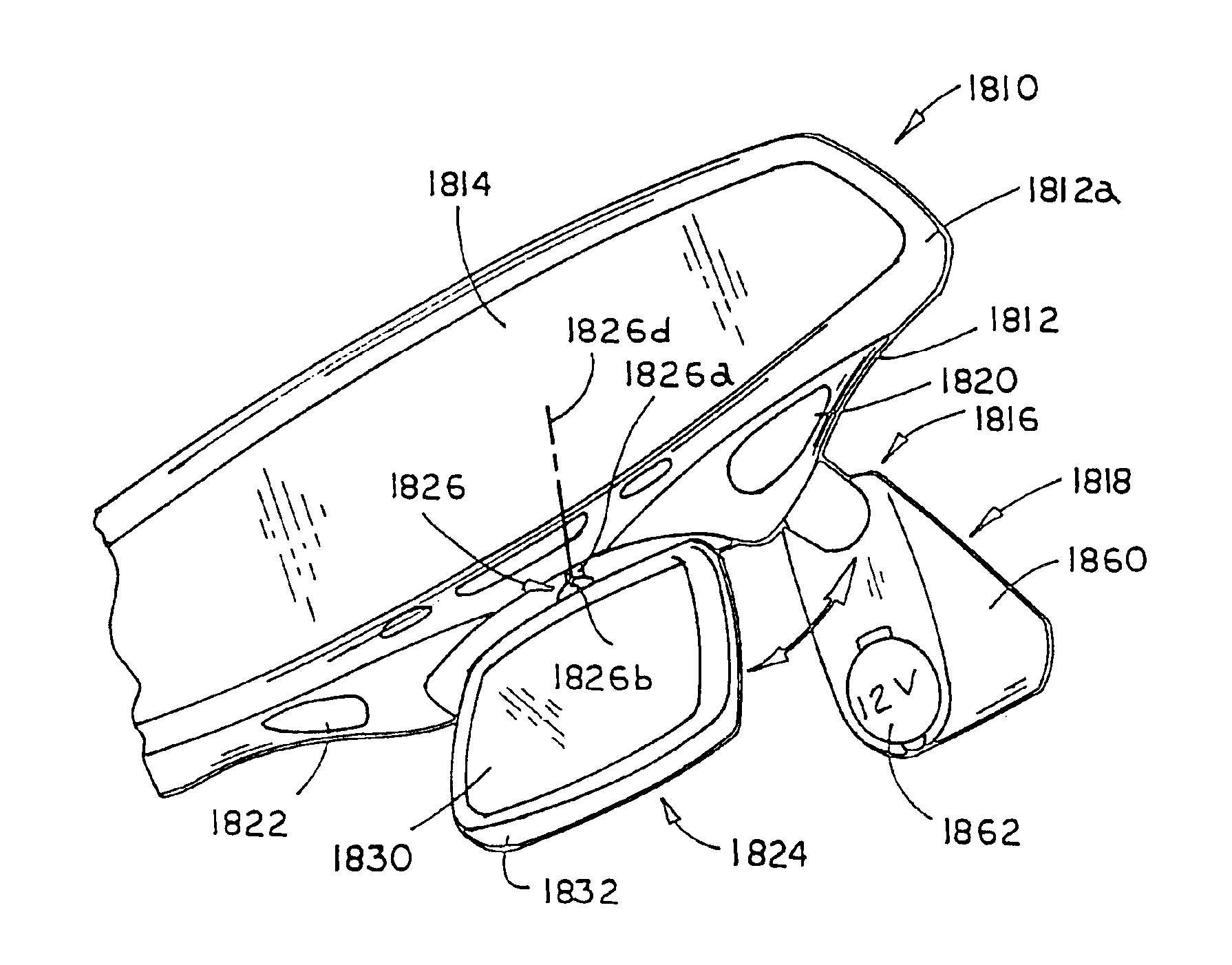
[0185]Referring to FIG. 33, the numeral 1610 generally designates the interior rearview mirror assembly illustrated in FIGS. 9-14. Mirror assembly 1610 includes a mirror housing or casing 1612, reflective element 1614, and a storage space 1622 for storing a dockable accessory 1624, similar to the previous embodiment. As previously described, dockable accessory 1624 may comprise a light assembly (shown), a telecommunications device, such as a phone or a pager or other hand held electrical or electronic devices. For further details of housing 1612, reflective element 1614 and accessory 1624, general reference is made to assembly 110.
[0186]Storage space 1622 is formed by a generally planar wall 1626 formed on back wall 1612a of casing 1612 and a generally open cavity 1628 which is formed in back wall 1612a and has a generally U-shaped configuration. Cavity 1628 is defined between planar wall 1626 and a generally U-shaped retaining wall 1628a which extends over planar wall 1626. Accesso...
third embodiment
[0206]Referring to FIG. 40, a light module drive circuit 1742″ is illustrated. Circuit 1742″ comprises a capacitor powered light module circuit and includes a capacitor 1758″ and an AC / DC converter 1760″, which controls the output voltage of capacitor 1758″. Drive circuit 1742″ also includes a light source circuit 1762″ which includes an on / off switch 1764″, a load current limiter resistor 1766″ and light source(s) 1734″ which are connected in series to AC / DC converter 1760″. In addition, flashlight circuit 1742″ preferably includes a safety switch 1768″ across capacitor 1758″ to discharge the capacitor 1758″ in the event housing 1730 of light module 1715 is open. Preferably, circuit 1742″ also includes a shock protection diode 1770″ and a charge current limiter resistor 1772″. Circuit 1742″ is connected to the vehicle power supply via a second AC / DC converter 1744″ and only requires two contacts-one to ground and the other to the vehicle power supply. In this manner, when dockable ...
PUM
 Abstract
Description
Claims
Application Information
 - R&D
- Intellectual Property
- Life Sciences
- Materials
- Tech Scout
- Unparalleled Data Quality
- Higher Quality Content
- 60% Fewer Hallucinations
Browse by: Latest US Patents, China's latest patents, Technical Efficacy Thesaurus, Application Domain, Technology Topic, Popular Technical Reports.
© 2025 PatSnap. All rights reserved.Legal|Privacy policy|Modern Slavery Act Transparency Statement|Sitemap|About US| Contact US: help@patsnap.com


