System and method for improved material processing using a laser beam

a laser beam and material technology, applied in laser surgery, medical science, surgery, etc., can solve the problems of gas gas emissions, eye defects, and variable or undesired outcomes, and achieve the effect of improving material processing and reducing or reducing the effect of gas emissions

Inactive Publication Date: 2005-06-07
AMO DEVMENT
View PDF20 Cites 106 Cited by
  • Summary
  • Abstract
  • Description
  • Claims
  • Application Information

AI Technical Summary

Benefits of technology

[0015]In accordance with the present invention, a method and system have been developed for improved material processing using photodisruptive lasers. The method includes the steps of directing a laser beam at a starting point above, at or below the surface of a material and thereafter moving the laser beam from the starting point along a preferred predetermined path to reduce or mitigate effects of gas, debris and other by-products created during photodisruption in the region where additional laser pulses are being placed.
[0016]In one embodiment of the present invention, the preferred predetermined path has a starting point in a particular region of the material that reduces or mitigates effects of gas, debris and other by-products created during photodisruption in a more critical region of the material. As an example of this embodiment, the predetermined path may begin at the circumference of the pattern to be placed on or in the material to reduce or mitigate effects of gas, debris and other by-products created during photodisruption in the center of the pattern. Examples of this embodiment include moving the focal point along a predetermined path in a spiral pattern that starts at the predetermined circumference of the internal surfaces and runs toward the center of the predetermined circumference. In another embodiment, the predetermined path is in the shape of a raster pattern that runs back-and-forth through the material from a starting point near the predetermined circumference toward the opposite side of the predetermined circumference. In a third embodiment, the focal point of the laser beam is moved along a predetermined path in the shape of a series of concentric circles that runs from the starting point at or near the predetermined circumference toward the center of the predetermined circumference. While these embodiments localize the effects of gas, debris, and other by-products created at the start of photodisruption to the circumference of a pattern, the opposite effect can be chosen by choosing a starting point at the center of a pattern.
[0017]In another embodiment of the invention, material processing can be influenced through creation of a secondary pattern (with its own preferred pattern or predetermined path), that is connected or adjacent to the primary predetermined path. Gas, debris and other by-products created during photodisruption in the primary predetermined path can be significantly reduced or eliminated from the region of further laser pulse placement through creation of these so-called reservoirs.

Problems solved by technology

The presence of gas, liquid, debris and other by-products created during photodisruption in the region where additional laser pulses are being placed can be a cause of variable or undesired outcomes.
One common cause for vision impairment results from a defective condition of the eye which occurs when the refractive characteristics of the cornea do not cause parallel rays of light to focus on the retina.
Both myopic and hyperopic conditions result in varying degrees of vision impairment.
It has been observed in some cases that moving the laser beam along a predetermined path or pattern creates a temporary cloudy appearance, which is believed to result from gas and / or debris created during the photodisruption process that spreads inside the tissue because there are no outlets for the gas and debris.
Both the cloudy appearance and the less effective effects of ensuing laser pulses are considered undesirable.
This fluid may result in surface irregularities that reduce the smoothness of the newly-created internal surface.

Method used


Image

  • System and method for improved material processing using a laser beam
  • System and method for improved material processing using a laser beam
  • System and method for improved material processing using a laser beam

Examples


Embodiment Construction

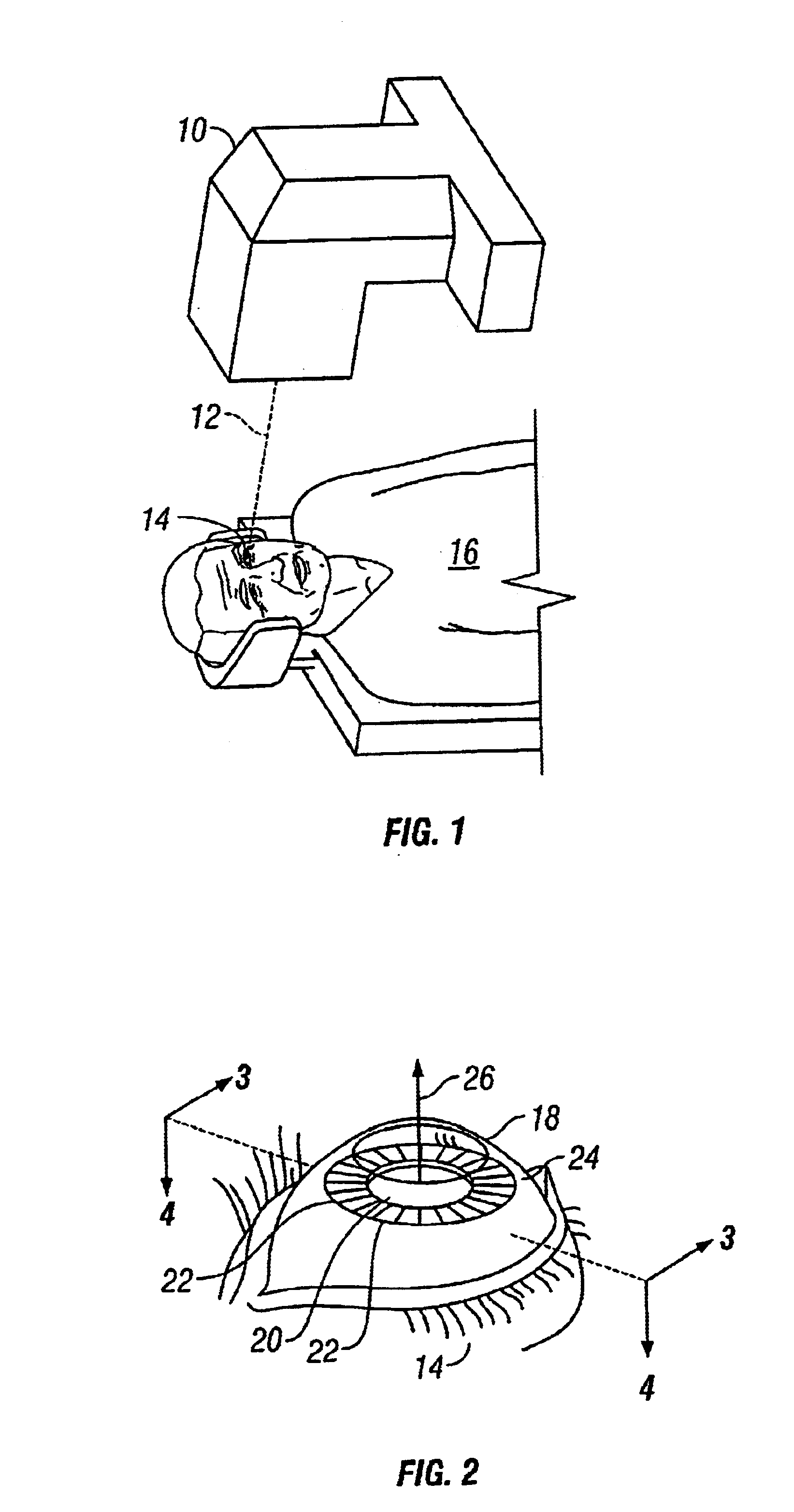
[0043]Referring initially to FIG. 1, an apparatus 10 for generating a laser beam 12 is shown. The laser beam 12 is directed onto an eye 14 of a patient 16. For purposes of the present invention, the apparatus 10 is capable of generating a pulsed laser beam 12 having physical characteristics similar to those of the laser beams generated by a laser system as disclosed and claimed in U.S. Pat. No. 4,764,930, which is exclusively licensed to the assignee of the present invention. Furthermore, the present invention contemplates the use of a pulsed: laser beam 12 which has pulses with durations as long as a few nanoseconds or as short as only a few femtoseconds.

[0044]In one embodiment, a laser unit is controlled by software for photodisruption of the cornea utilizing a laser beam of constant energy, composed of an optical train of pulses with a duration of approximately 600 femtoseconds at a repetition rate of up to several hundred thousand Hz. The actual energy in the emitted pulse train...


PUM


Abstract

A method and system for improved material processing using a laser beam. The method and system includes directing a laser beam above, at or below the surface of the material in one or more preferred patterns and with preferred laser pulse characteristics specific to the material to reduce or mitigate the accumulation or effects of gas, debris, fluid, or other by-products of photodisruption either at the location where additional laser pulses are being placed or in other sensitive locations in the material.

Description

RELATED APPLICATIONS[0001]This application claims priority to U.S. provisional patent application 60 / 367,119 filed Mar. 23, 2002.FIELD OF THE INVENTION[0002]The present invention pertains generally to the field of material processing with a laser beam and more particularly to systems and methods for improved processing of these materials. The present invention is particularly useful for material processing utilizing laser photodisruption as a mechanism of action, particularly when such processing involves the use of multiple laser pulses placed on or below the surface of a material. While the field of the invention is very wide, it is particularly useful as a system and method for utilizing a laser beam to form a series of overlapping photodisrupted areas inside a material to define a new internal surface so that the anterior portion of the material can be moved to have access to the new internal surface of the material. A particular example of this application is in a type of ophth...

Claims


Application Information

Patent Timeline
Patent Type & Authority Patents(United States)
IPC IPC(8): A61F9/01A61F9/007
CPCA61F9/008A61F9/00827A61F9/00836A61F2009/00897A61F2009/00872
Inventor KURTZ, RONALD M.JUHASZ, TIBORGOLDSTEIN, PETERHEGEDUS, IMREHORVATH, CHRISTOPHERSCHOLLER, GORDON S.BERG, ALAN W.
Owner AMO DEVMENT
Why Eureka
Try Eureka