Method of making elemental materials and alloys

a technology applied in the field of production of elemental materials and alloys, can solve the problems of significant heat generation, and achieve the effect of reducing the environmental impact of the process

Inactive Publication Date: 2005-06-07
TRONOX LLC
View PDF34 Cites 30 Cited by
  • Summary
  • Abstract
  • Description
  • Claims
  • Application Information

AI Technical Summary

Benefits of technology

[0021]Additionally, the present invention is particularly beneficial in connection with reduction reactions that produce elemental materials and alloys from the exothermic reduction of precursor materials, and preventing the substances that are produced from sintering onto the

Problems solved by technology
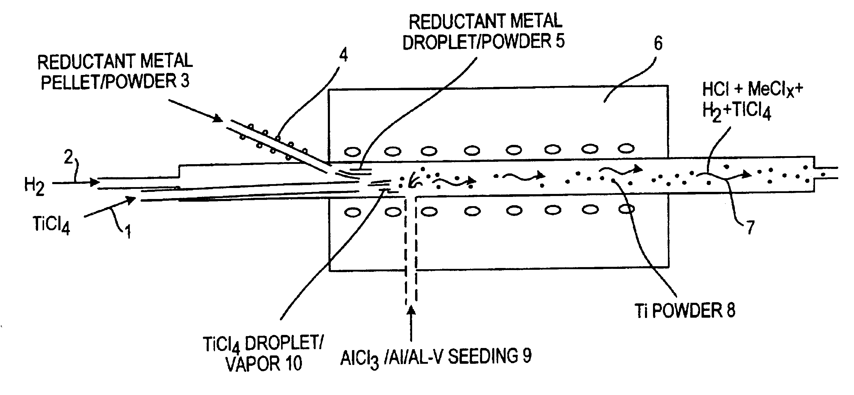
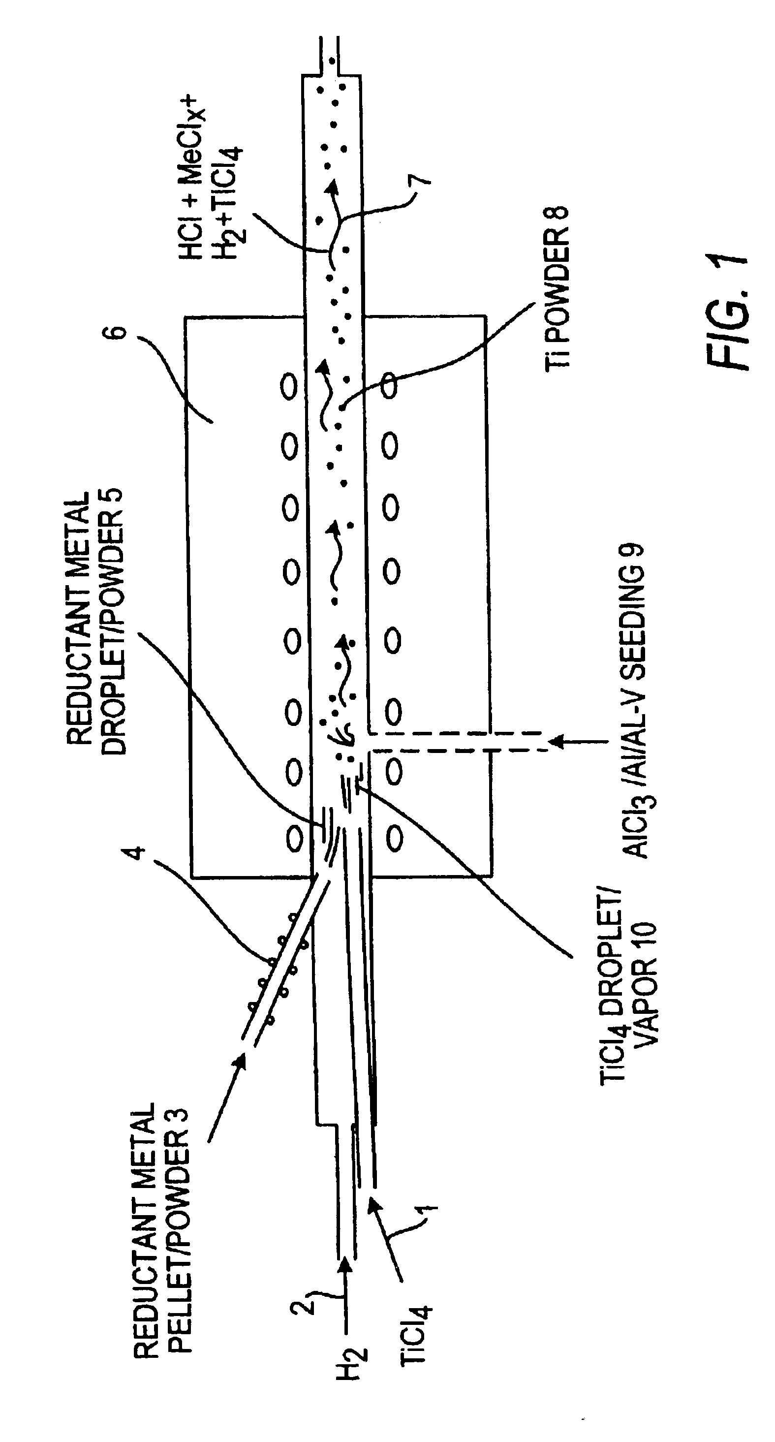
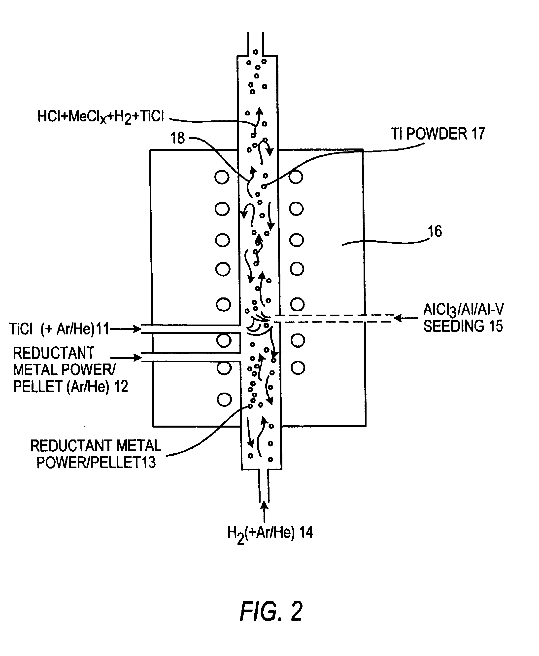
Preferably, according to the methods for producing these materials, accompanying the

Method used


Image

  • Method of making elemental materials and alloys
  • Method of making elemental materials and alloys
  • Method of making elemental materials and alloys

Examples


example 1

[0088]1 g of Mg powder, (Alfa Aesar, −325 mesh (4 reduction by H2. The experiment was carried out by the procedures described above at the temperature of 600° C. for 30 min then at 700° C. for 20 min.

[0089]After the experiment, the color of the 2-mm surface powders in the crucible changed from original gray to black, and their particle sizes changed to 0.5-2 mm. Most of the powders in the bottom of the crucible still retained their original color and size of the Mg powder, while some particles with metallic shining color and sub-millimeter size existed among them, which could be seen by naked eyes. Many particles in the diameters of sub millimeters with black or metallic shining colors were found in the downstream reaction tube and the Sampling Vessel. The samples were separately collected from the crucible and the Sampling Vessel and analyzed by scanning electron microscopy coupled with energy dispersive X-ray (SEM-EDX) and X-ray diffraction spectroscopy (XRD).

[0090]SEM-EDX detecte...

example 2

[0091]A control experiment was carried out to confirm the function of and the route through the reducing gas, for example, H2, for the present invention. The experiment was conducted in the same way as example 1 except that Ar substituted H2 (no H2 was used at all). After the experiment, no particle was found in the Sampling Vessel and downstream tubes, which was different from the result of example 1, where a certain amount of the particles were founded from the Sampling Vessel and the downstream tube. Therefore, as discussed above, the particles in the Sampling Vessel and the downstream tube in example 1 were produced via the TiCl4 reduction through H2.

example 3

[0092]The experimental condition used was the same as Example 1 except that the reaction was carried out at 900° C. for 30 min then at 1000° C. for 20 min. After the experiment, the color and size of all of the powders in the crucible were changed. In the crucible orientation, the color of all of the powders in the upstream half (about 35 mm long) of the crucible became black, while the color of the powders in the downstream half (˜35 mm long) of the crucible became white. Most of the powders in the crucible were in the size range of sub-millimeters to 2 millimeters. SEM-EDX detected the black powders contained about 75% of titanium and about 5% of Mg, and the white powders contained about 70% of Mg and 2% Ti. The black powder was metallic titanium, while the white powder was MgCl2. Similar to Example 1, SEM-EDX also indicated that the powders collected from the Sampling Vessel and the downstream tubes contained about 50% of titanium but no magnesium at all.


PUM

PropertyMeasurementUnit
Fractionaaaaaaaaaa
Timeaaaaaaaaaa
Temperatureaaaaaaaaaa

Abstract

A method of producing an elemental material or an alloy thereof from a halide or mixtures of halides is provided. The halide or mixtures thereof are contacted with a reducing gas in the presence of reductant material, preferably in sufficient quantity to convert the halide to the elemental material or alloy and to maintain the temperature of the reactants at a temperature lower than the boiling point of the reductant material at atmospheric pressure or the sintering temperature of the produced elemental material or alloy.

Description

FIELD OF THE INVENTION[0001]The present invention relates to the field of the production of elemental materials and alloys.BACKGROUND OF THE INVENTION[0002]Often it is desirable to obtain substances in their elemental forms or high quality alloys of these substances in order to use them in certain high-end applications, for example, sports and leisure activities. However, in nature most substances are not readily accessible in their elemental forms.[0003]For example, frequently titanium occurs in ores as a dioxide or mixed oxide with iron. Because of titanium's affinity for gases and most metals in the periodic table, it is quite difficult to extract elemental titanium from its ores. Consequently, in order to obtain elemental Ti, complex and now well-known processes have been developed. Unfortunately, these processes, as well as similar processes for obtaining other elemental materials can be cumbersome and costly.[0004]Many naturally occurring substances either exist as halides or ...

Claims


Application Information

Patent Timeline
IPC IPC(8): C22B5/04C22B34/12C22B5/00C22B34/00
CPCC22B5/04C22B34/1286C22B34/1277C22B34/1272
Inventor NIE, JASON X.DANIELS, ROBERTPERKINS-BANKS, DALE H.MESSER, THOMAS
Owner TRONOX LLC
Why Eureka
Try Eureka