Overflow transfer furnace and control system for reduced oxide production in a casting furnace

a technology of overflow transfer furnace and control system, which is applied in the direction of liquid transfer device, heat treatment apparatus, manufacturing converter, etc., can solve the problems of requiring a significant amount of maintenance to prevent the leakage of molten metal at the stopper rod. , to achieve the effect of reducing the production of oxides and reducing the number of movable parts

Inactive Publication Date: 2005-06-07
SHIPSTON ALUMINUM TECH MICHIGAN
View PDF24 Cites 87 Cited by
  • Summary
  • Abstract
  • Description
  • Claims
  • Application Information

AI Technical Summary

Benefits of technology

[0012]The present invention allows for the introduction of molten metal, for example, aluminum, of a uniform temperature to a casting furnace with a reduced production of oxides. The transfer apparatus has a reduced number of movable parts that are subject to submersion in the molten metal or aluminum. The present invention also allows for the automated delivery of molten metal or aluminum on demand into a casting furnace by means of a controlled overflow of a transfer furnace. The present invention further allows the transfer of metal to a casting furnace largely independently of the overall level of molten metal in the launder.

Problems solved by technology

While the stopper rod box is a simple system with few moving parts, a significant amount of maintenance is required to prevent leakage of molten metal at the stopper rod.
The components of the stopper box are located underneath molten aluminum, which makes them inaccessible during operations and difficult to maintain without shutting down the process.
Poor maintenance can result in metal leaks at the discharge point and result in costly and time-consuming cleanup.
While neither pump has any moving parts, the enclosed nature of these pumps makes periodic cleaning very time consuming.
If the level of molten aluminum in the launder drops too dramatically, the amount of metal in the transfer furnace will be insufficient to provide an adequate volume of molten metal to the casting furnace.
Transfer via either a stopper rod box or current pumping technology exposes the molten metal to atmospheric oxygen unnecessarily.
In addition, the temperature of the metal that is discharged from the transfer furnace can vary and may further contribute to undesirable properties of the finished cast metal.

Method used


Image

  • Overflow transfer furnace and control system for reduced oxide production in a casting furnace
  • Overflow transfer furnace and control system for reduced oxide production in a casting furnace
  • Overflow transfer furnace and control system for reduced oxide production in a casting furnace

Examples


Embodiment Construction

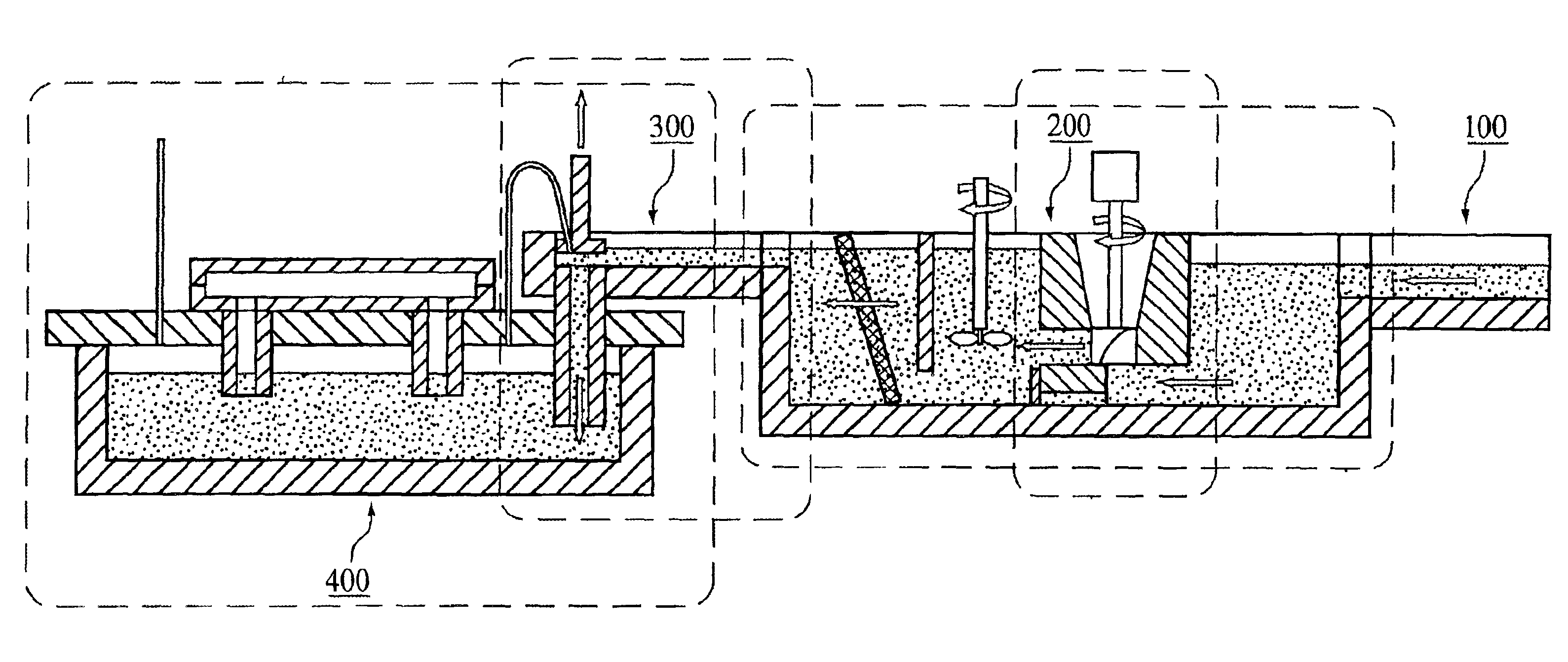
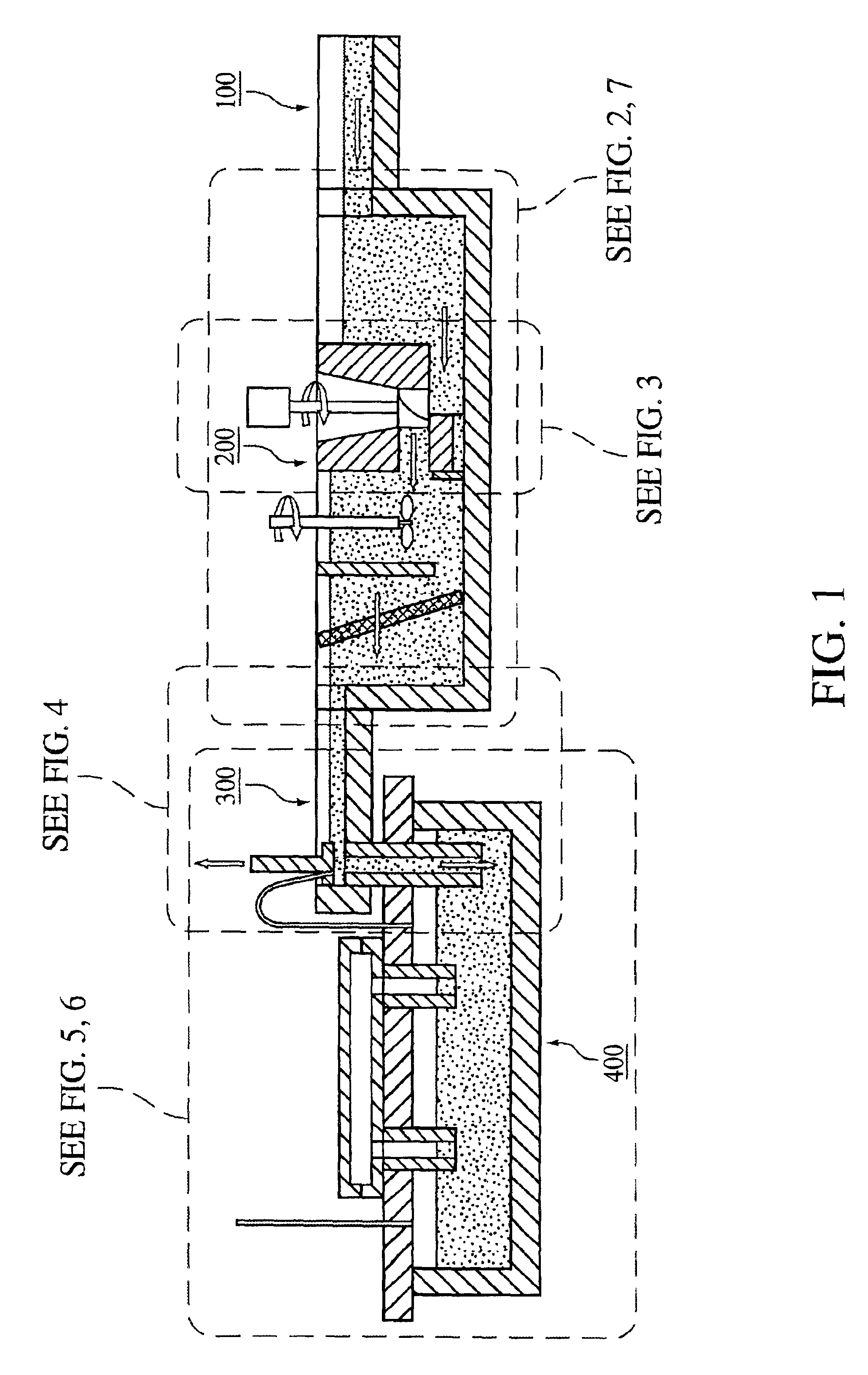
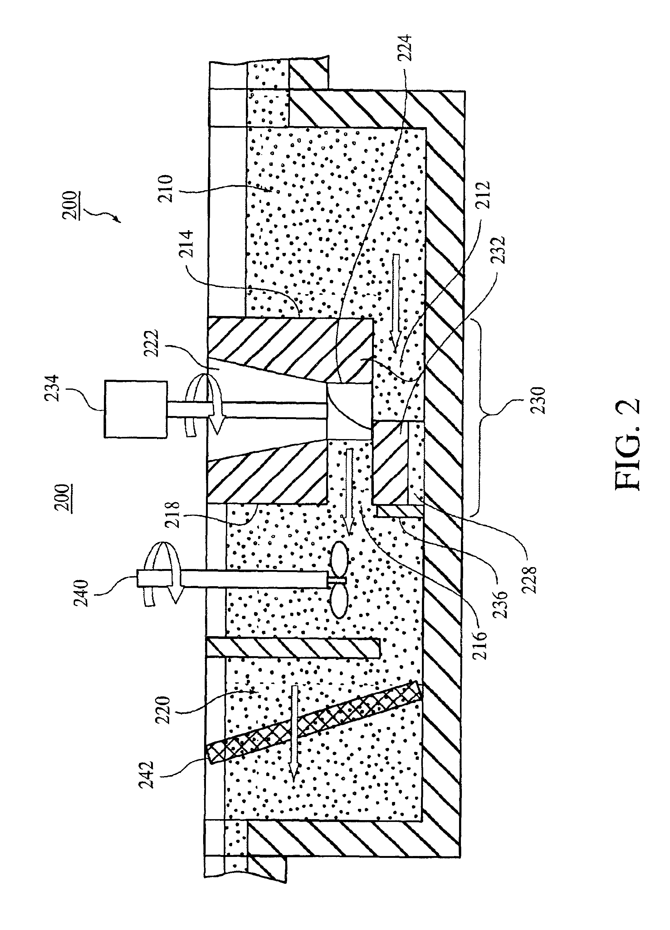
[0023]The present invention now will be described more fully hereinafter with reference to the accompanying drawings, in which preferred embodiments of the invention are shown. This invention may, however, be embodied in many different forms and should not be construed as limited to the embodiments set forth herein; rather, these embodiments are provided so that this disclosure will be thorough and complete, and will fully convey the scope of the invention to those skilled in the art.

[0024]In the drawings, like numbers refer to like elements throughout. It will be understood that when a feature, such as a surface layer, region or component is described as being “on” another element, it can be directly on the other element or intervening elements may also be present. Further, terms such as “upstream,”“downstream” or like terms as used herein, refer to the relative positions of components based upon the flow of molten metal.

[0025]The term “adjacent” is used throughout in the broadest ...


PUM

PropertyMeasurementUnit
melt levelaaaaaaaaaa
speedaaaaaaaaaa
temperatureaaaaaaaaaa

Abstract

An apparatus for transferring molten metal from a melting furnace to a casting furnace is provided. A sensing and control system for the transfer of molten metal from a transfer furnace to a casting furnace is also described. The combination of the transfer apparatus with the sensing and control system provides for the introduction of reduced oxide molten metal into a casting furnace.

Description

FIELD OF THE INVENTION[0001]The present invention relates to transfer furnaces, systems and methods for providing molten metal to a casting furnace. The devices and methods of the present invention enable the transfer of molten metal from a launder to a casting furnace such that there is a reduction in the production of metal oxides or dross and a reduction of wasted molten metal.BACKGROUND OF THE INVENTION[0002]Delivery of molten metal, such as aluminum or aluminum alloys (collectively referred to herein as aluminum), to a casting furnace is a multi-step process. Initially, aluminum ingots may be melted in a melting furnace and the molten aluminum may then be dispensed from the melting furnace to a launder. In such an arrangement, the molten aluminum flows from the launder to a holding furnace (transfer furnace) where its temperature is preferably maintained prior to being introduced into a casting furnace.[0003]While the molten aluminum is present in the transfer furnace, it may b...

Claims


Application Information

Patent Timeline
Patent Type & Authority Patents(United States)
IPC IPC(8): C22B21/00
CPCC22B21/0084
Inventor KLINGENSMITH, MARSHALL A.KINOSZ, MICHAEL J.BORNS, RICK A.
Owner SHIPSTON ALUMINUM TECH MICHIGAN
Why Eureka
Try Eureka