
Display assembly with contrast inversion including two superposed display devices

a display device and display assembly technology, applied in the field of display assembly including two superposed display devices, can solve the problems of unsatisfactory energy saving system solutions, unsatisfactory in the field of contrast inversion, and large complication of mechanical or manual drive systems, so as to reduce the undesirable parallax effect

Inactive Publication Date: 2005-06-07
ASULAB SA
View PDF18 Cites 37 Cited by
  • Summary
  • Abstract
  • Description
  • Claims
  • Application Information

AI Technical Summary

Benefits of technology

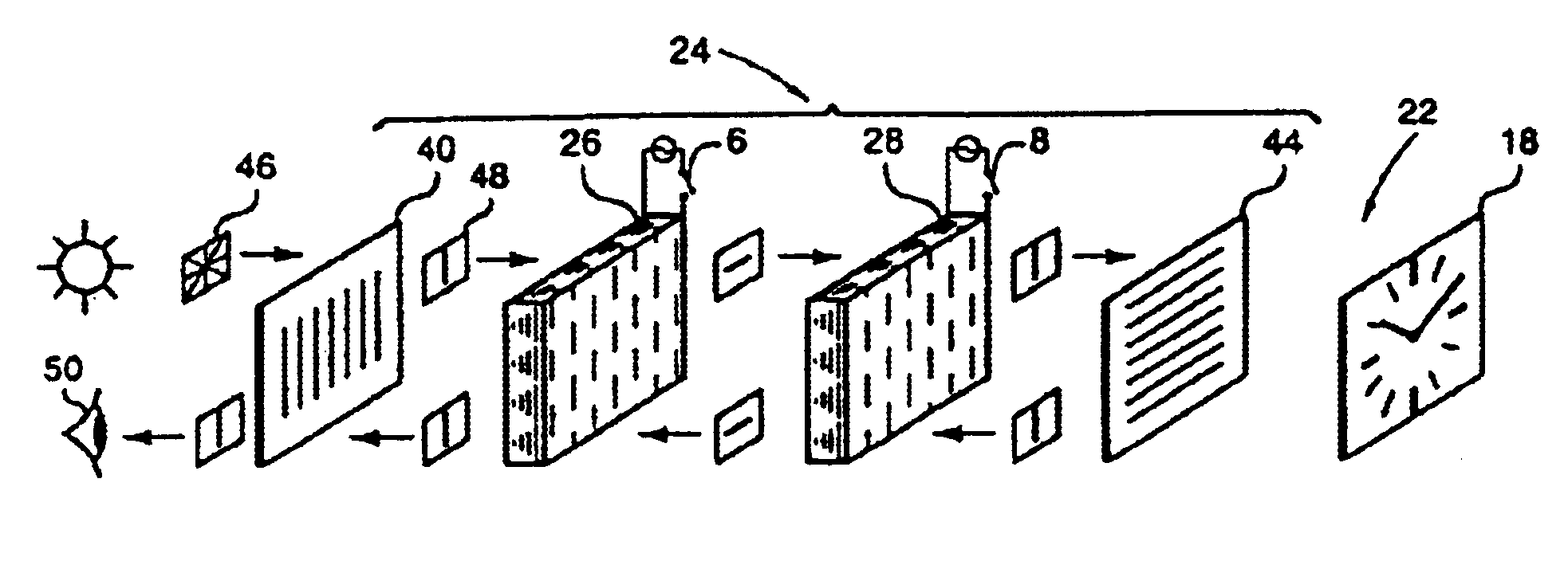
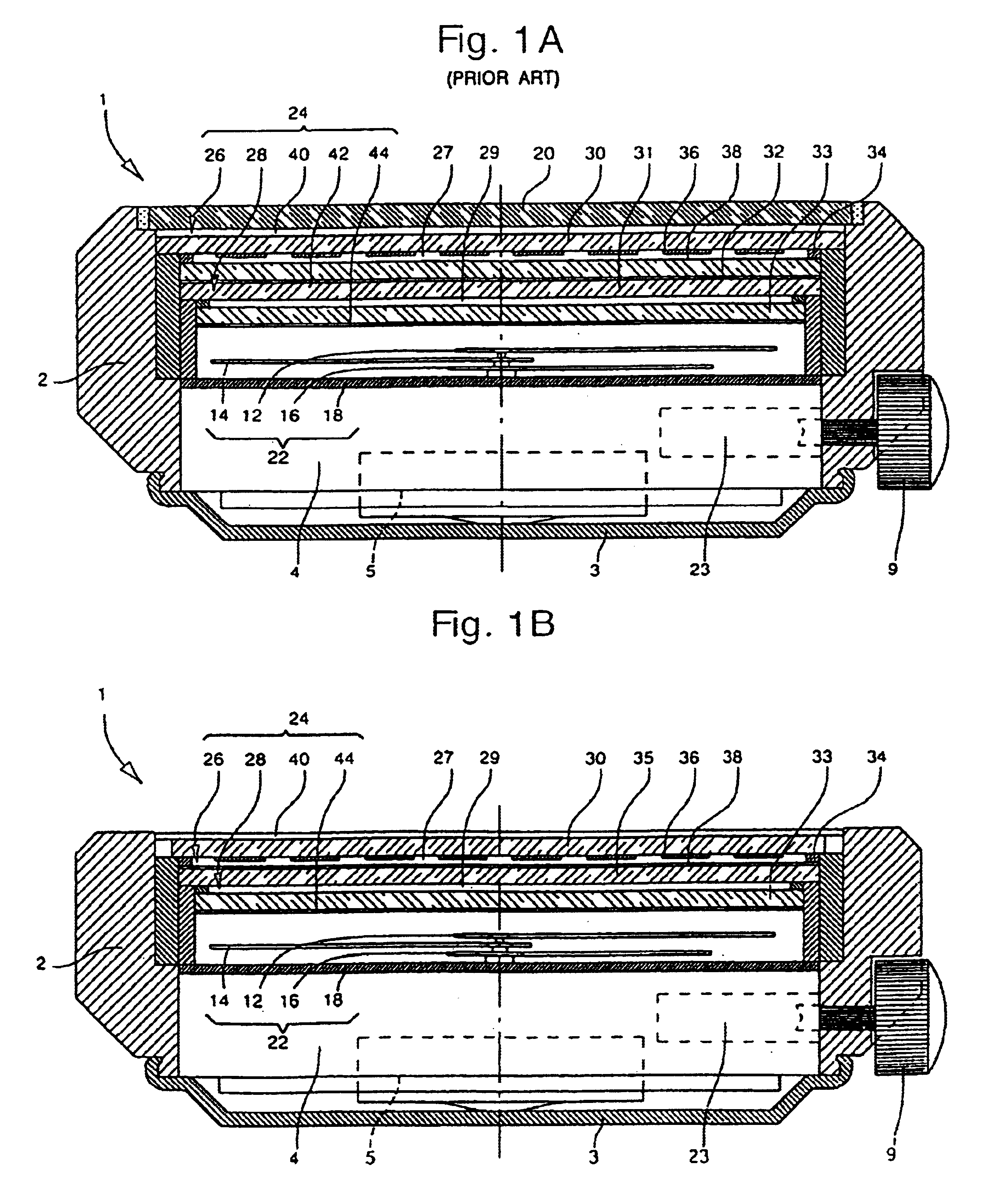
[0025]According to a further aspect of the invention, if there is no polariser between the display cell and the optical valve, it is possible to construct the second display device with a transparent median substrate common to the display cell and the optical valve, thereby reducing the undesirable parallax effect.
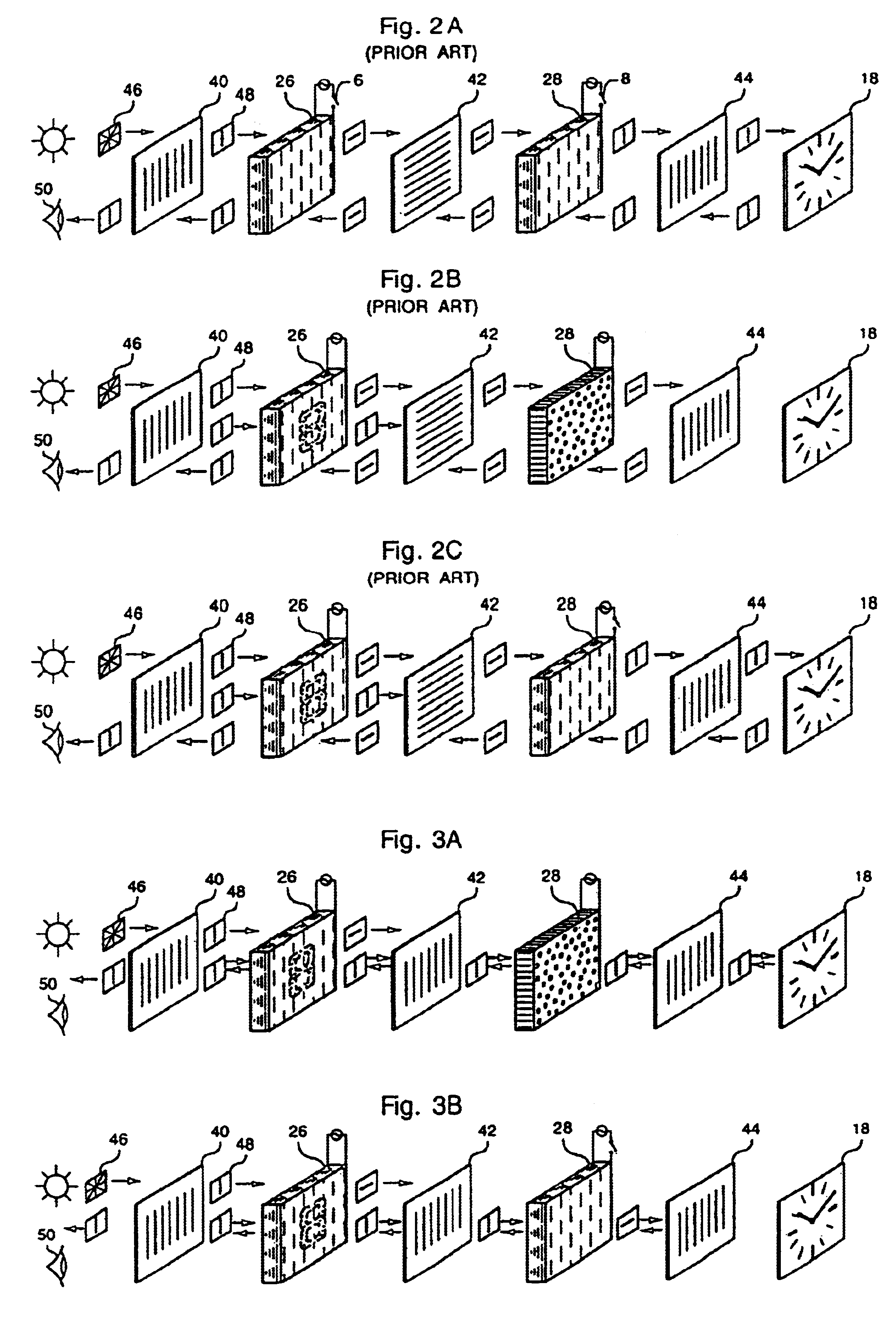
[0027]The invention also has the advantage of allowing the user to select the type of contrast best suited to the lighting of the place in which he is situated, namely a dark colour on a light background if there is not much light, or conversely a light colour on a dark background if there is a lot of light.

Problems solved by technology

As can be seen, whatever the positive or negative anisotropy of the twisted nematic liquid crystals, the passage from an OFF-OFF switching configuration to an ON-ON switching configuration does not allow an inversion of the contrast to be obtained.
In a known manner, such a contrast inversion could be obtained by means of inverse addressing, but at the cost of a demand for energy nine times greater than that which is necessary to address only {fraction (1 / 10)} of the useful segments for the display, a solution which is unsatisfactory in a system where energy saving is of great importance.
Likewise, according to the teaching of the prior art, one could hope to obtain an inversion of the contrast by rotating a polariser by 90°, which would obviously cause great complication as regards a mechanical or manual drive system, especially for a display assembly of small dimensions, such as that able to be incorporated in a wristwatch.

Method used


Image

  • Display assembly with contrast inversion including two superposed display devices
  • Display assembly with contrast inversion including two superposed display devices
  • Display assembly with contrast inversion including two superposed display devices

Examples


Embodiment Construction

[0039]The following description is made by way of example within the scope of an application of the invention to a timepiece such as a wristwatch of the type shown in FIG. 1. It is to be understood that the invention is not limited to this application and that it could advantageously be used within the scope of any other application, such as measuring or animation instruments for which an inversion of the contrast of all or part of the displayed data might be useful, aesthetically pleasing or surprising.

[0040]The actual construction of the two superposed display devices inside a wristwatch will not be described any further, given that, in its most general embodiment, it corresponds to what was already described with reference to FIG. 1A, with the exception of intermediate polariser 42 which has been omitted.

[0041]In the case of an application to a wristwatch, the first display device will essentially display time related data and the second display device will display time related d...


PUM

PropertyMeasurementUnit
rotationaaaaaaaaaa
transparentaaaaaaaaaa
anisotropyaaaaaaaaaa

Abstract

A second device (24) is mounted on a first device (22) formed of a liquid crystal (27) display cell (26) at the front of which is arranged a first linear polarizer (40), of a liquid crystal (29) optical valve (28) at the back of which is arranged a second polarizer (44) and means (23) for controlling the valve (28) and the cell (26) from a switched state to a non switched state. When the cell (26) is switched to display a data item, by associating a first light or dark device (22) with a second absorbent or reflective polarizer (44), an inversion of the contrast in said data is obtained by switching the valve (28).

Description

FIELD OF THE INVENTION[0001]The present invention concerns a display assembly including two superposed display devices, a first display device farthest from the observer being surmounted by a second display device formed by a liquid crystal cell assembly and polarisers including control means to make visible either solely the information given by the second display device offering the possibility of inverting the contrast of all or part of said information, or the information given by the first display device.BACKGROUND OF THE INVENTION[0002]The invention also concerns a timepiece provided with such a display assembly wherein the first display device is formed for example by the dial of the timepiece and the second display device is arranged between the crystal and the dial or merged with the crystal. The invention concerns more particularly such a timepiece wherein the dial cooperates with an analogue display.[0003]According to another aspect of the invention, the information given...

Claims


Application Information

Patent Timeline
Patent Type & Authority Patents(United States)
IPC IPC(8): G02F1/13G02F1/1347G04G9/00G02F1/1335G02F1/133G04C3/00G04GG09F9/46
CPCG04G9/0082G02F1/13471G02F1/133533G02F1/133536
Inventor BASTURK, NACI
Owner ASULAB SA
Learn More