Internal riser inspection device

a riser inspection and inspection device technology, applied in the direction of instruments, material magnetic variables, specific gravity measurements, etc., can solve the problems of drilling rigs not being able to operate, time-consuming to transport, inspect and reassemble the riser sections, and high cost of transportation

Inactive Publication Date: 2005-06-14
HYDRIL USA DISTRIBUTION LLC
View PDF33 Cites 69 Cited by
  • Summary
  • Abstract
  • Description
  • Claims
  • Application Information

AI Technical Summary

Benefits of technology

[0014]For the auxiliary lines, a smaller diameter unit is utilized. In this unit, multiple shoes are employed, but more than one transducer may be mounted to each shoe. The shoe is spring biased rather that urged by a pneumatic cylinder.

Problems solved by technology

The transport of the riser sections to a testing facility on land is expensive.
Also, it is time consuming to transport, clean, disassemble, inspect and reassemble the riser sections.
During this time, unless a spare drilling riser can be obtained, the drilling rig would not be able to operate.
Drilling rigs are very costly on a daily basis.
However, there are a number of problems in doing so.
The interior of the drilling riser is often not very clean, and may be coated with dried drilling mud.
Also, there is normally not much access room on the drilling rig at the ends of each riser section for staging the equipment necessary to do the inspection.

Method used


Image

  • Internal riser inspection device
  • Internal riser inspection device
  • Internal riser inspection device

Examples


Embodiment Construction

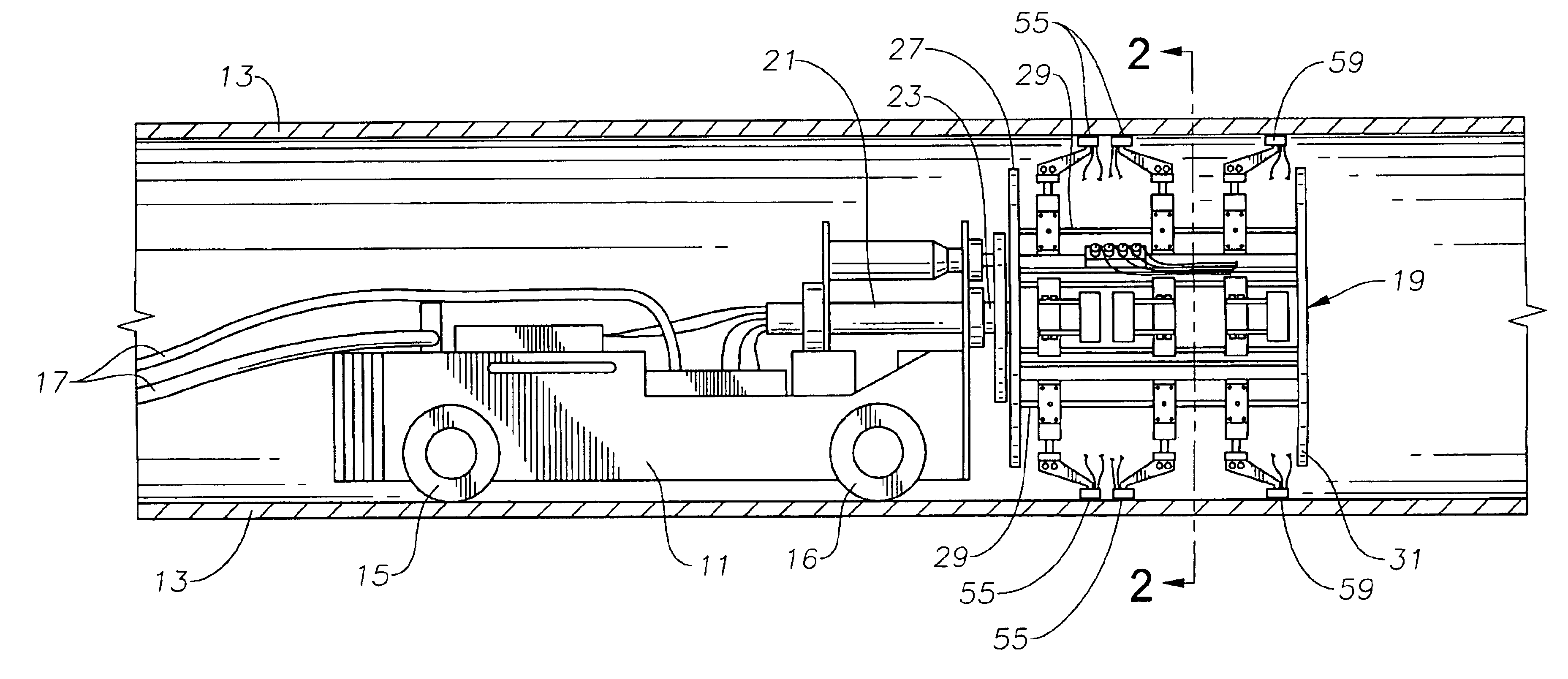
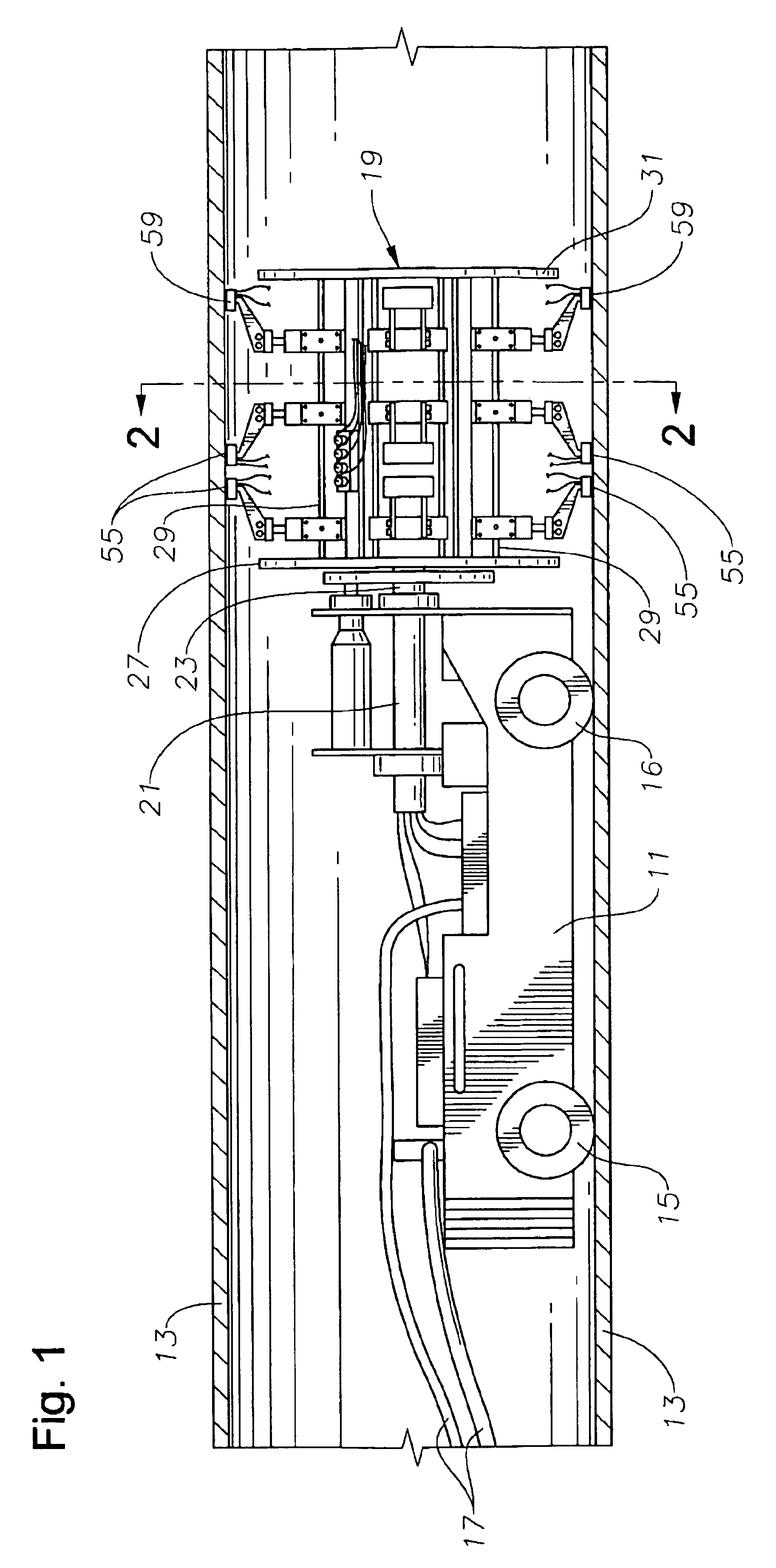
[0029]The inspection device of FIG. 1 has a self-propelled drive unit 11, which is shown within a central pipe 13 of a riser section. Drive unit 11 has two drive wheels 15 and two support wheels 16, which are spaced axially from drive wheels 15. Drive unit 11 is controlled and supplied with water by a plurality of lines 17 that extend out the end of pipe 13. The operator has controls for causing drive unit 11 to move forward and backward by providing signals through some of the lines 17.

[0030]The operator also has an odometer display that displays an indication of the linear distance that drive unit 11 is located from a zero point at the end of riser section 13. Encoder 18 (FIG. 5), which is mounted to the axle of support wheels 16, provides this information. Encoder 18 is preferably a conventional unit that uses a light beam that passes through a large number of apertures formed in a disc, the disc rotating with support wheels 16. Support wheels 16 are not driven, rather they freew...


PUM

PropertyMeasurementUnit
lengthaaaaaaaaaa
diameteraaaaaaaaaa
depthaaaaaaaaaa

Abstract

An internal inspection unit for pipe has ultrasonic transducers that inspect weld volume, weld root, and wall thickness. The ultrasonic transducers are mounted to a portion of the inspection unit that is rotatable, but no more than one full revolution. One of the units has independently movable shoes for each separate transducer. The shoes are moved between retracted and extended positions by pneumatic cylinders. The other unit has shoes that support more than one transducer, the shoes being biased outwardly by springs.

Description

[0001]This application claims the provisional application filing date of Apr. 5, 2002, Ser. No. 60 / 370,444 entitled “Internal Riser Inspection Device.”FIELD OF THE INVENTION[0002]The invention relates in general to non-destructive testing of pipe, and in particular to a test unit that is conveyed internally through pipe for ultrasonically inspecting the pipe wall thickness and welds.BACKGROUND OF THE INVENTION[0003]Non-destructive testing of pipe has been done for many years utilizing ultrasonic transducers, eddy current measurements, x-ray and other techniques. Operators using pulse echo techniques with ultrasonic transducers can determine wall thickness, which is a measure of any corrosion that has occurred. For welds, operators have used flight diffraction (“TOFD”) techniques with ultrasonic transducers. Also, a method known as pulse echo shear wave has been combined with TOFD transducer measurements to inspect portions of the weld that are missed by the TOFD transducer.[0004]One...

Claims


Application Information

Patent Timeline
Patent Type & Authority Patents(United States)
IPC IPC(8): G01N27/72G01B17/02G01M19/00G01N29/24G01N29/04G01N29/00G01N21/88G01R33/12G01FG01M99/00G01N29/07G01N29/22G01N29/265
CPCG01B17/02G01N29/069G01N29/07G01N29/225G01N29/265G01N2291/2675G01N2291/02854G01N2291/105G01N2291/2636
Inventor HARTHORN, LARRY K.DIOQUINO, PEDRO A.MILLIGAN, JR., RICHARD J.GOOD, JASON C.ALLEN, NEIL D.ROMERO, RICHARD D.
Owner HYDRIL USA DISTRIBUTION LLC
Why Eureka
Try Eureka