Modular internal combustion engines

a technology of internal combustion engine and module, which is applied in the direction of valve drive, combustion air/fuel air treatment, machine/engine, etc., can solve the problems of inability to interchange the major engine housing components, such as castings or other housing components, between different types of single and/or twin cylinder engines, and the difficulty of assembling the belt to the drive and the driven pulley, so as to reduce the number of total components

Inactive Publication Date: 2005-06-14
TECUMSEH POWER
View PDF78 Cites 14 Cited by
  • Summary
  • Abstract
  • Description
  • Claims
  • Application Information

AI Technical Summary

Benefits of technology

[0018]Further, the cylinder members may also be used in single cylinder engines to form side valve or “L-head” horizontal or vertical crankshaft engines, or OHV horizontal or vertical crankshaft engines. In this manner, the cylinder members are modular components which may be used in either twin cylinder engines or in single cylinder engines, thereby reducing the number of total components which are needed to produce a line of single cylinder and two cylinder engines, as well as the costs associated with manufacturing the line of single and twin cylinder engines.

Problems solved by technology

A disadvantage with existing engine designs is that the castings or housing portions which contain known single and twin cylinder engines have a specific construction which is unique to each of the single and twin cylinder engines.
Although certain minor engine components, such as valves, valve springs, carburetors, etc., might possibly be used in a number of different engines, interchangeability of major engine housing components, such as castings or other housing components, between different types of single and / or twin cylinder engines is not possible.
In these engines, assembling the belt to the drive and the driven pulleys can be difficult during the manufacturing process.

Method used


Image

  • Modular internal combustion engines
  • Modular internal combustion engines
  • Modular internal combustion engines

Examples


Embodiment Construction

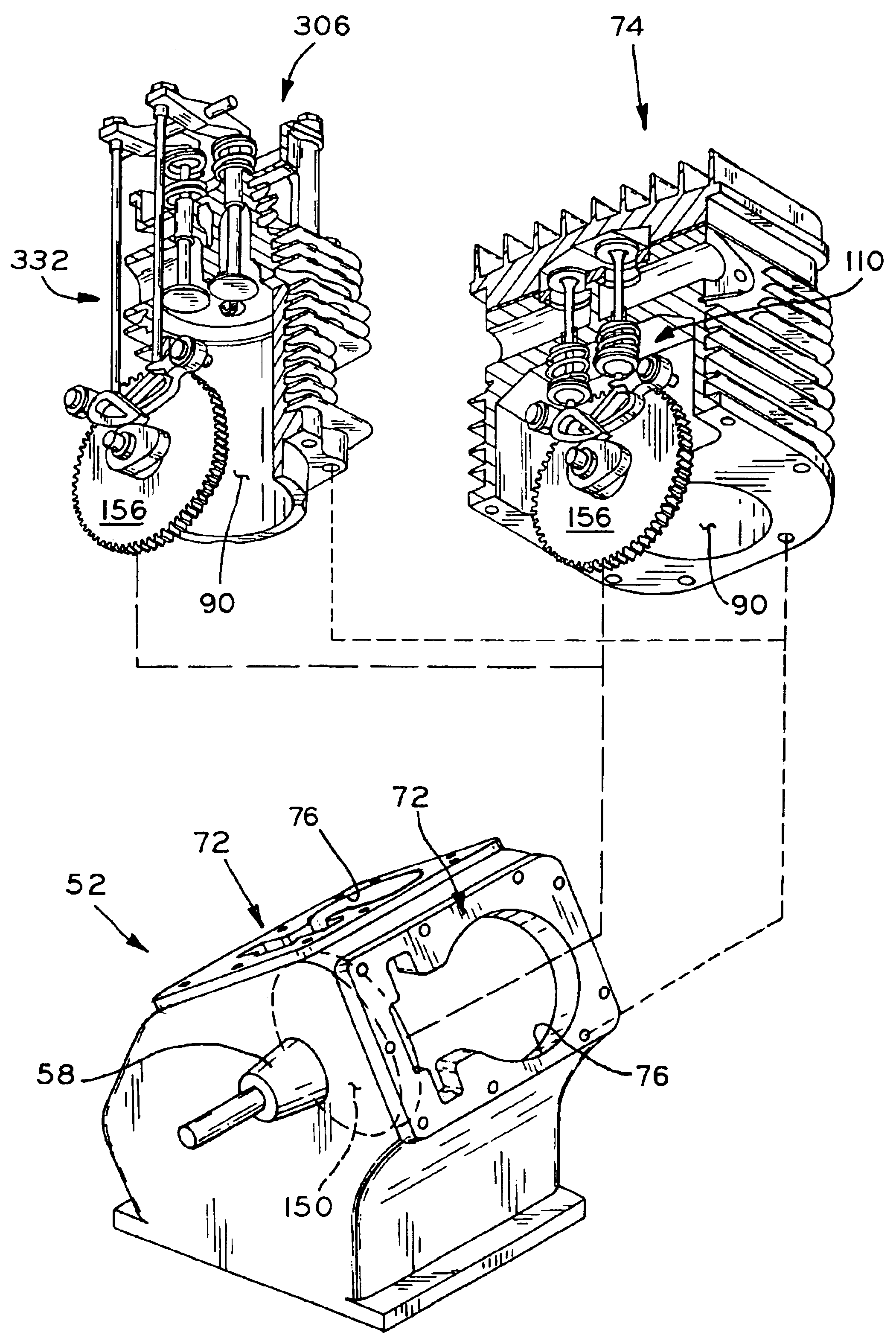
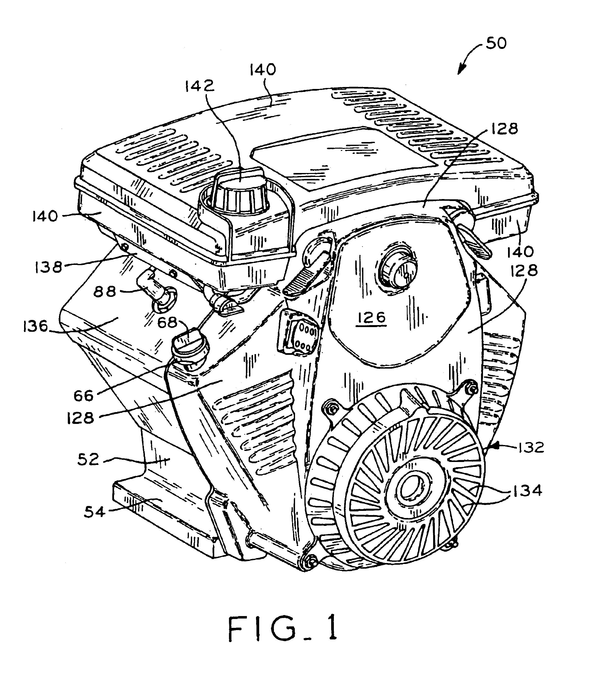
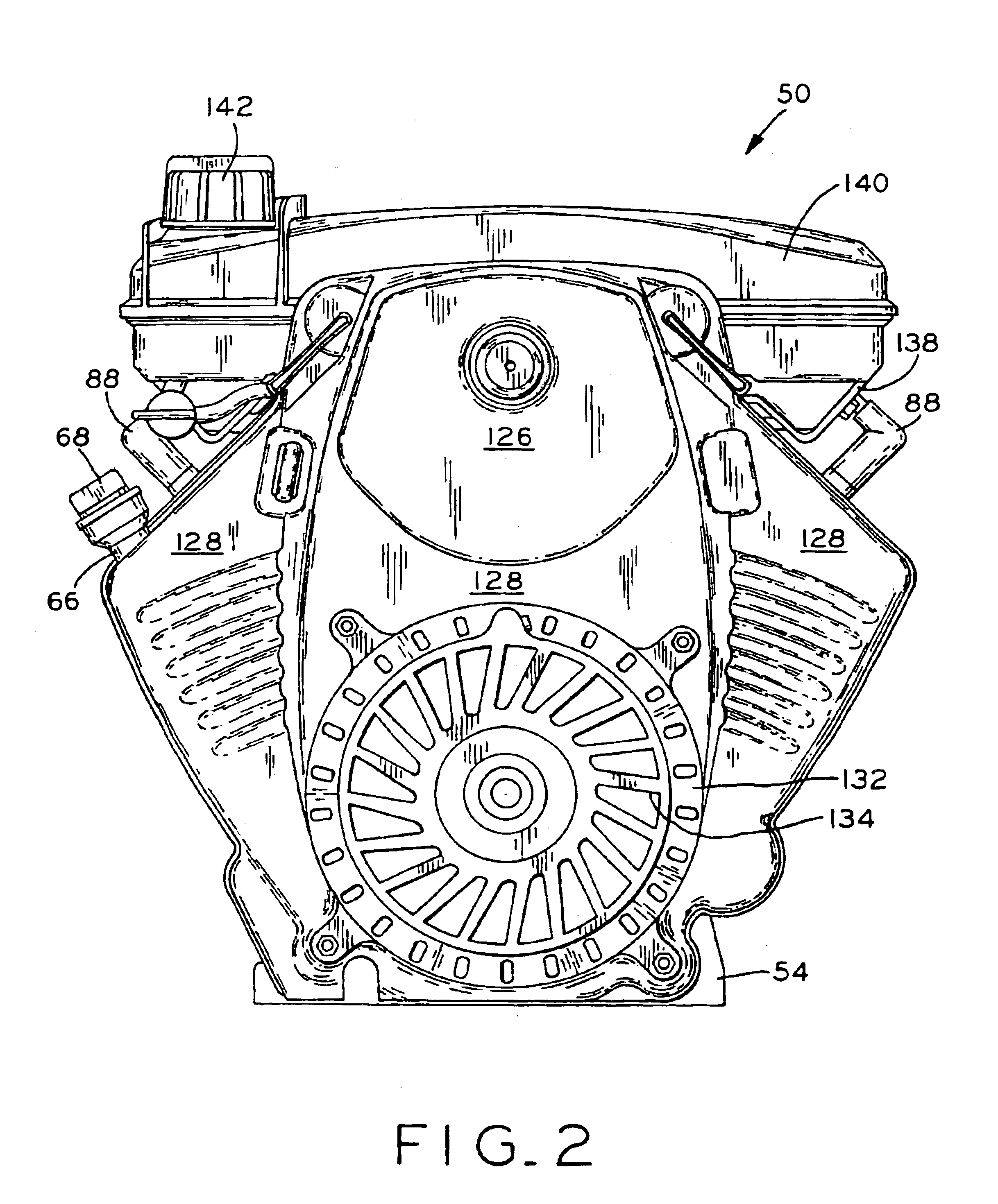
[0057]Referring to FIGS. 1-7, a first internal combustion engine 50 is shown as a horizontal crankshaft, V-twin engine having a side valve or “L-head” valve train, as discussed in detail below. However, engine 50 may, with minor modifications, also be configured as a vertical crankshaft, V-twin engine having a side valve or “L-head” valve train, as shown in FIG. 14. Also described below is engine 300, shown in FIGS. 15-24 which is similar to engine 50, and which may be configured as a horizontal or vertical crankshaft V-twin engine having an overhead valve (“OHV”) valve train. Further, the cylinder members of engines 50 or 300 may also be used in a twin cylinder opposed engine such as engine 400 shown in FIG. 25. Still further, a cylinder member of engines 50 or 300 may be used in a vertical or a horizontal crankshaft single cylinder engine, such as engines 500, 600, and shown in FIGS. 26, 27, and 28, respectively.

[0058]Referring first to FIGS. 1, 6, and 7, engine 50 includes crankc...


PUM

PropertyMeasurementUnit
angleaaaaaaaaaa
angleaaaaaaaaaa
areaaaaaaaaaaa

Abstract

A line of small internal combustion engines, including twin cylinder engines and single cylinder engines. The engines each include a crankcase, and one or more cylinder members attached to the crankcase, the cylinder members being separate components from the crankcase. A number of different crankcases are provided for various types of single and two cylinder engines, the crankcases having common mounting structure to which the cylinder members may be attached. Thus, the manner in which the cylinder members are attached to the crankcases is the same for each of the different types of crankcases. Two different types of cylinder members are provided, one having a side valve or “L-head” valve train, and the other having an overhead cam (“OHV”) valve train. The cylinder members are therefore modular components which may be selectively used in a variety of different types of engines.

Description

CROSS REFERENCE TO RELATED APPLICATIONS[0001]This application is a continuation-in-part of U.S. patent application Ser. No. 10 / 409,262 entitled INTERNAL COMBUSTION ENGINE, filed on Apr. 8, 2003, which claims the benefit under Title 35, U.S.C. §119(e) of U.S. Provisional Patent Application Ser. No. 60 / 372,560, entitled INTERNAL COMBUSTION ENGINE, filed on Apr. 15, 2002, and U.S. Provisional Patent Application Ser. No. 60 / 402,841, entitled INTERNAL COMBUSTION ENGINE, filed on Aug. 12, 2002.BACKGROUND OF THE INVENTION[0002]1. Field of the Invention[0003]The present invention relates to small internal combustion engines, which are used in a variety of applications, such as lawnmowers, lawn and garden tractors, other small working implements such as snow throwers and generators, or in sport vehicles.[0004]2. Description of the Related Art[0005]Small internal combustion engines typically include one or two engine cylinders. Single cylinder engines generally have a valve train of the side ...

Claims


Application Information

Patent Timeline
Patent Type & Authority Patents(United States)
IPC IPC(8): F01B1/00F01B1/12F01L1/04F01L1/047F02B75/16F01L1/02F01L1/20F02B63/02F01L1/18F01L1/14F02B75/22F01L1/08F02B75/00F02F1/26F02F1/30F02M35/02F02B63/00F02M35/024F02B75/18F02B75/02F02F7/00
CPCF01B1/12F01L1/024F01L1/04F01L1/047F01L1/08F01L1/146F01L1/18F01L1/20F02B63/02F02B75/16F02B75/22F02F1/30F02F7/0031F02M35/024F01L1/02Y10T29/49231F01L1/026F02B2075/027F02B2075/1808F02B2275/22Y10T29/4927
Inventor SNYDER, DALE D.IMMEL, THOMAS A.KOEHLER, SCOT A.STANELLE, GARYMONIS, KARL W.GLODOWSKI, MARK J.DOPKE, RUSSELL J.KRAGH, PAUL J.
Owner TECUMSEH POWER
Why Eureka
Try Eureka