Method of manufacturing an integral rotor blade disk and corresponding disk

Inactive Publication Date: 2005-06-14
SN DETUDE & DE CONSTR DE MOTEURS DAVIATION S N E C M A
View PDF9 Cites 50 Cited by
  • Summary
  • Abstract
  • Description
  • Claims
  • Application Information

AI Technical Summary

Benefits of technology

[0013]An important advantage of the invention is the possibility of leaving an outer annulus joining the ends of the blade blanks, which plays a part in stiffening them and holding them during milling, thereby greatly reducing vibration and flexing. The annulus is a vestige of the disk in the raw state and is therefore integral with the blades; it is parted from them by a final machining operation undertaken after the blades have been given their definitive shape.
[0014]A blisk produced in accordance with the invention has a characteristic shape having faces of the blades formed of substantially radial longilinear facets. Such a blisk may be obtained by the method which has just been explained, but it is not excluded for i

Problems solved by technology

It has the disadvantage of giving faceted blade surfaces, with a coarser appearance and which give rise to poorer flow, but it

Method used


Image

  • Method of manufacturing an integral rotor blade disk and corresponding disk
  • Method of manufacturing an integral rotor blade disk and corresponding disk
  • Method of manufacturing an integral rotor blade disk and corresponding disk

Examples


Embodiment Construction

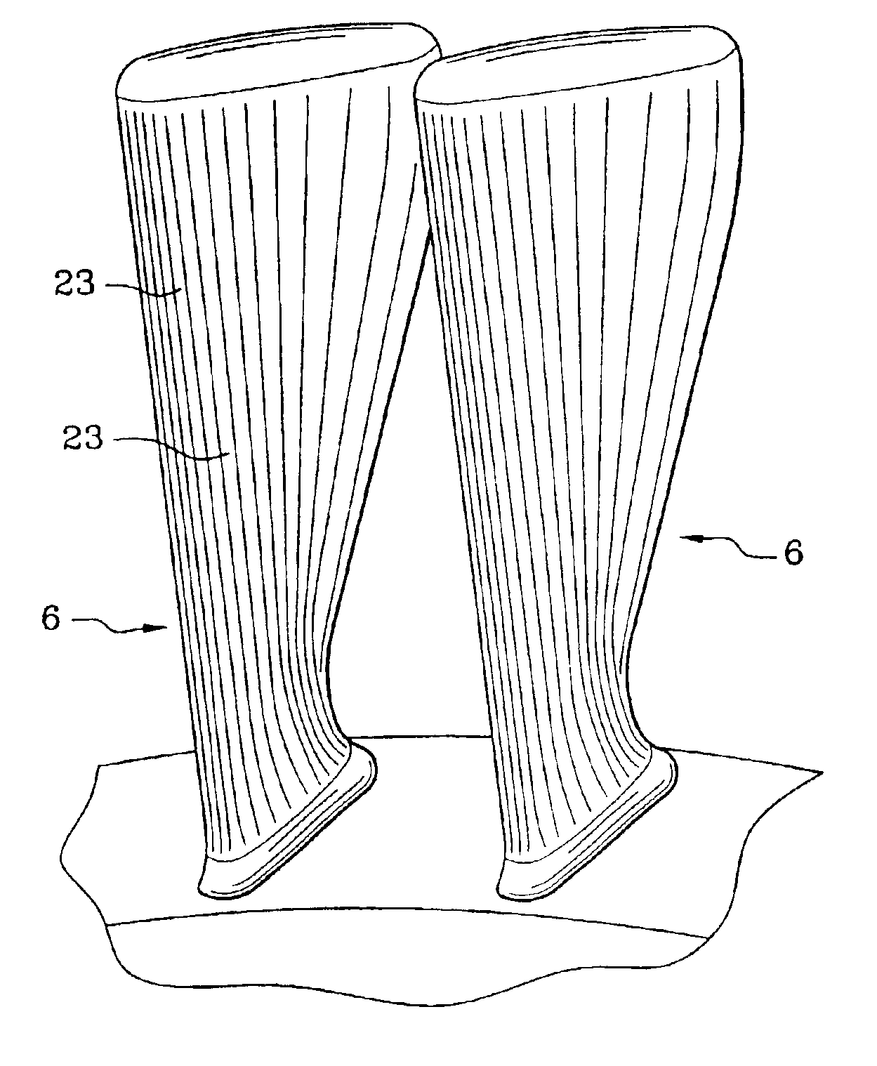
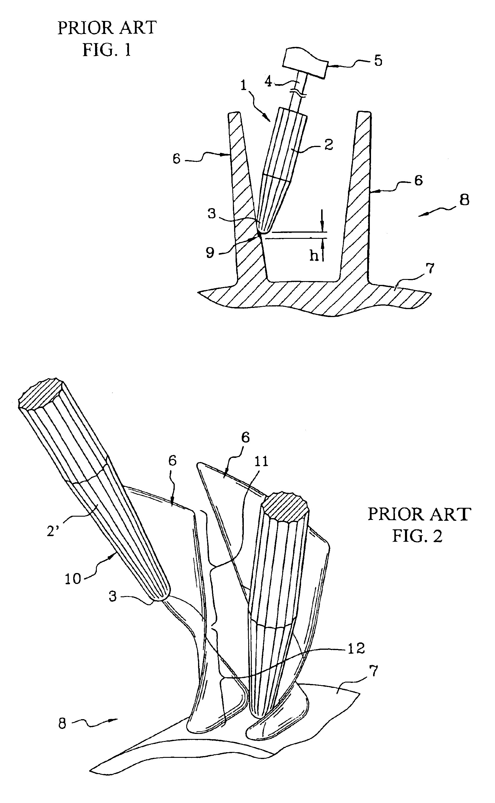
[0025]Milling cutters traditionally used for machining blades, such as the one generally indicated at 1 in FIG. 1, comprise a conical main part 2 ending in a rounded and more specifically hemispherical, tip 3. The main part 2 and the tip 3 are each covered with cutting teeth, and the milling cutter 1 rotates about a rotation spindle 4 driven by a numerically controlled machine 5 which is not depicted in detail. The tip 3 is applied to a blade 6 which, with other similar blades and a hub 7, makes up a blisk in the process of being machined. The spindle 4 and the milling cutter 1 have a substantially radial orientation with a small tangential inclination (with respect to the disk 8). The milling cutter 1 is moved at right angles to the page, making successive passes at respective heights along the blade 6, these passes being separated by heights such as h, the reference 9 denoting the section of the blade 6 which will be removed in the next pass.

[0026]The milling cutter in FIG. 2 is i...


PUM

PropertyMeasurementUnit
Angleaaaaaaaaaa
Angleaaaaaaaaaa
Widthaaaaaaaaaa

Abstract

A method of manufacturing a blisk comprises the steps of cutting a disk to a rough shape comprising a hub with a plurality of blade blanks projecting radially therefrom, machining each blade blank by tangential milling using a tool with a rotation spindle perpendicular to the radial direction to make repeated radial passes, the tool being turned through a facet angle with respect to the disk between each pass. Each blade blank is thus milled to a blade having faceted surfaces. Preferably, the width of each facet is smaller that 5 mm, and adjacent facets subtend angles smaller than 5°, or even more preferably smaller than 3°.

Description

BACKGROUND OF THE INVENTION[0001]1. Field of the Invention[0002]This invention relates to a method of manufacturing an integral rotor blade disk, commonly referred to as a blisk and to blisks of characteristic shape produced in accordance with the method. A blisk comprises a hub and a plurality of blades integrally projecting substantially radially therefrom.[0003]2. Summary of the Prior Art[0004]The machining of the blades of a blisk from a solid disk in the raw state involves preliminary machining of the disk using a milling cutter with a large radius to leave blade blanks that have to be machined more finely to a definitive shape. It is common practice to resort to milling to perform this fine machining. Milling cutters used for this purpose have a special conical shape, and taper toward a rounded end allowing high-precision machining operations to be performed.[0005]One known method is end milling in which the rotation spindle of the milling cutter is oriented radially with resp...

Claims


Application Information

Patent Timeline
IPC IPC(8): B23C3/18B23C3/00F01D5/00F01D5/14F01D5/34F01D5/02
CPCB23C3/18F01D5/34F01D5/147B23C2215/44Y10T29/49325
Inventor BOURGY, JOELDAVID, JEAN-PIERRE ANDREDENISDERRIEN, STEPHANE JEAN-DANIEL MAURICEMALEVILLE, THIERRY-JEAN
Owner SN DETUDE & DE CONSTR DE MOTEURS DAVIATION S N E C M A
Why Eureka
Try Eureka