Stator for down hole drilling motor

a technology for drilling motors and stators, which is applied to machines/engines, rotary/oscillating piston pump components, liquid fuel engines, etc., can solve the problems of low oil resistance, high manufacturing cost, and harsh environment of rubber stators in drilling motors, so as to reduce susceptibility to stator damage, improve sealing characteristics, and improve thermal degradation characteristics

Inactive Publication Date: 2005-06-14
HALLIBURTON ENERGY SERVICES INC
View PDF32 Cites 67 Cited by
  • Summary
  • Abstract
  • Description
  • Claims
  • Application Information

AI Technical Summary

Benefits of technology

[0008]The present invention provides an improved stator for a dynamic down hole drilling motor wherein the stator has improved thermal degradation characteristics. The invention provides a down hole motor with reduced susceptibility to stator damage from the rotor due to water swell of the stator. The preset invention provides a down hole motor with improved sealing characteristics and suff

Problems solved by technology

EPDM, a terpolymer, is highly resistant to weather, ozone and heat aging but is not oil resistant.
Rubber stators in down hole drilling motors are subjected to a harsh environment involving both higher temperatures, hydrocarbon immersion and dynamic loading.
However, such a hard material is difficult to injection mold, resulting in expensive manufacturing costs.
Thus, the prior art has not been able to achieve a satisfactory balance for use in down hole motors, regarding durability in operation but easier to manufacture.
U.S. Pat. No. 6,183,226 teaches that r

Method used


Image

  • Stator for down hole drilling motor
  • Stator for down hole drilling motor

Examples


Embodiment Construction

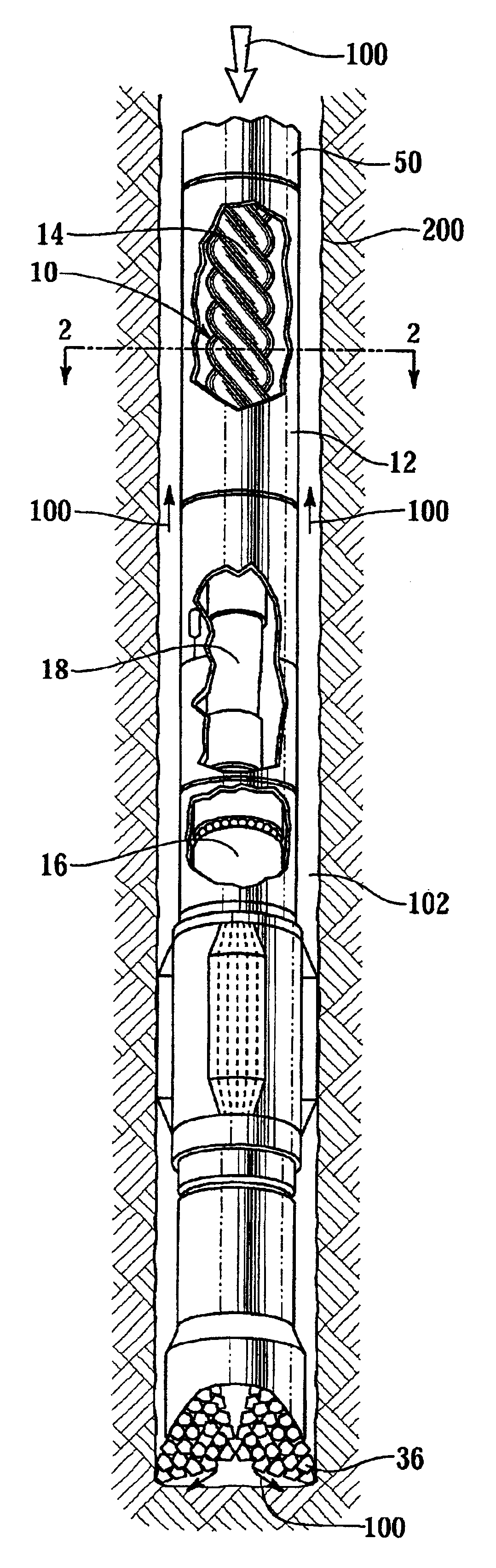
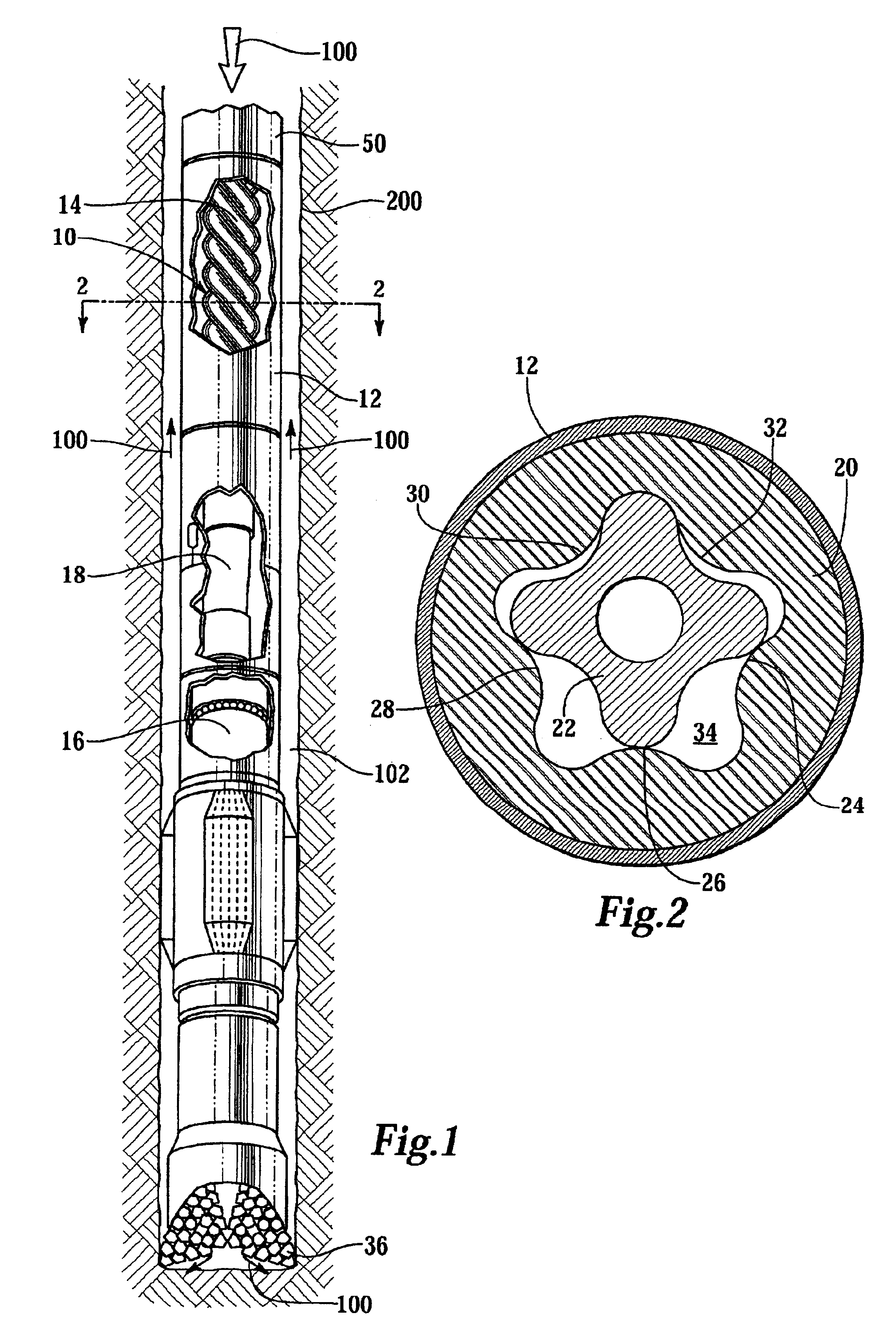
[0013]FIG. 1 depicts a down hole motor 10 according to one embodiment of the present invention. A down hole motor generally comprises a tubular housing 12 that is preferably formed of steel. Disposed within the tubular housing 12 is a power unit 14 connected to a bearing section assembly 16 via a transmission unit 18. The power unit 14 comprises a stator 20 and rotor 22, a cross-section of which is shown in FIG. 2. The stator preferably comprises a plurality of lobes (24, 26, 28, 30, 32) defining a cavity 34. It will be understood by those skilled in the art that there may be fewer or more lobes than the 5 illustrated herein. The rotor 22 is operatively positioned in the cavity 34 to cooperate with the plurality of lobes. Applying fluid pressure to the cavity 34 causes the rotor 22 to rotate in cooperation with the lobes in order to allow pressurized drilling fluid 100 that is introduced at an upper end of the pump to be expelled at the lower end and then subsequently exhausted from...


PUM

PropertyMeasurementUnit
Temperatureaaaaaaaaaa
Fractionaaaaaaaaaa
Fractionaaaaaaaaaa

Abstract

An improved down hole drilling motor suitable for drilling applications. The down hole drilling motor comprising a stator disposed in the tubular housing. The stator includes an internal cavity having one or more lobes. A rotor operatively positioned in the cavity of the stator is adapted to cooperate with the one or more lobes of the stator. The stator comprising a compound having improved manufacturing and performance characteristics.

Description

FIELD OF THE INVENTION[0001]This invention is directed generally toward down hole motors, and in particular down hole drilling motors used in oil and gas well drilling applications and the like.BACKGROUND OF THE INVENTION[0002]Progressing cavity motors, also known as Moineau-type motors (after the inventor of U.S. Pat. No. 1,892,217), including stator devices used therein, have been used in drilling applications for many years. See, for example, the following U.S. Pat. Nos. which are incorporated herein by reference: U.S. Pat. Nos. 3,840,080; 3,912,426; 4,415,316; 4,636,151; 5,090,497; 5,171,138; 5,417,281; 5,759,109; and 6,183,226.[0003]Conventional Moineau pump and motor art has used rubber or elastomer materials bonded to steel for the stator contact surface. Such elastomers include not only natural rubber, but also synthetics, such as G.R.S., Neoprine, Butyl and Nitrile rubbers and other types such as soft PVC. For example, U.S. Pat. No. 5,912,303, incorporated herein by referen...

Claims


Application Information

Patent Timeline
IPC IPC(8): F04C2/00F04C2/107F03C2/00F03C2/08
CPCF03C2/08F04C2/1075F05C2251/10F05C2251/02F05C2225/02
Inventor GUO, LILLIAN
Owner HALLIBURTON ENERGY SERVICES INC
Why Eureka
Try Eureka