

Rotary pump for braking apparatus
a braking apparatus and rotary pump technology, applied in the direction of braking systems, machines/engines, liquid fuel engines, etc., can solve the problems of increasing cost, increasing drive torque, and substantially increasing drive torque, and achieve the effect of increasing drive torqu
- Summary
- Abstract
- Description
- Claims
- Application Information
AI Technical Summary
Benefits of technology
Problems solved by technology
Method used
Image

Examples
first embodiment
[0062](First Embodiment)
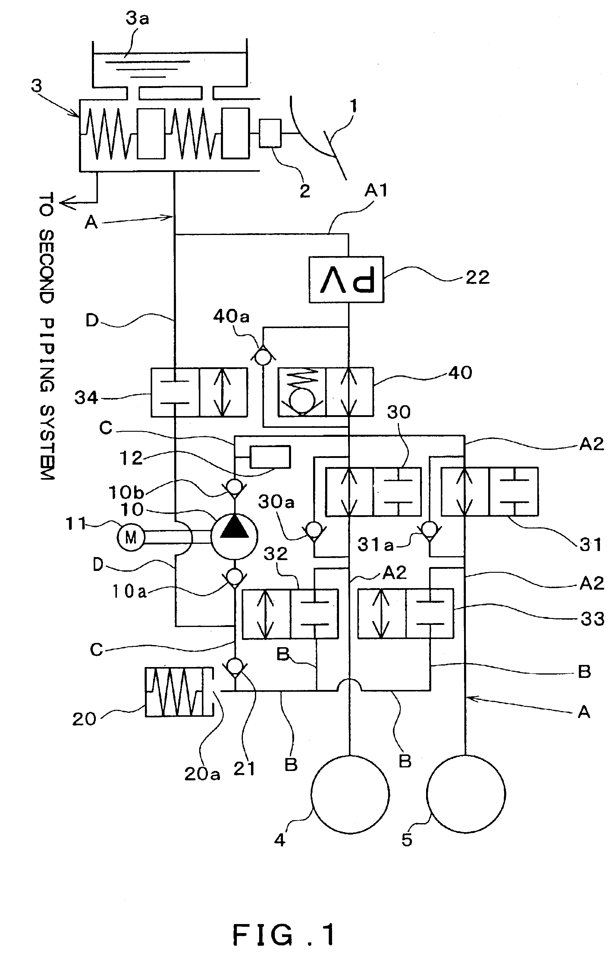
[0063]Hereinafter, a first embodiment will be explained with reference to the drawings. FIG. 1 is a schematic view of a brake piping system of a braking apparatus to which a trochoid pump has been applied as a rotary pump. A fundamental configuration of the braking apparatus will be explained with reference to FIG. 1. In the first embodiment, an example will be explained in which the braking apparatus according to the present invention is applied to a four-wheeled front-wheel-drive vehicle configured with a hydraulic circuit piping X that is provided with two piping systems, these being a front-right / rear-left wheel piping system and a front-left / rear-right wheel piping system, respectively.
[0064]As shown in FIG. 1, a brake pedal 1 is connected to a booster 2, and a brake depression force is increased by the booster 2. The booster 2 has a push rod that transmits the increased brake depression force to a master cylinder 3. A master cylinder pressure is generat...
second embodiment
[0111](Second Embodiment)
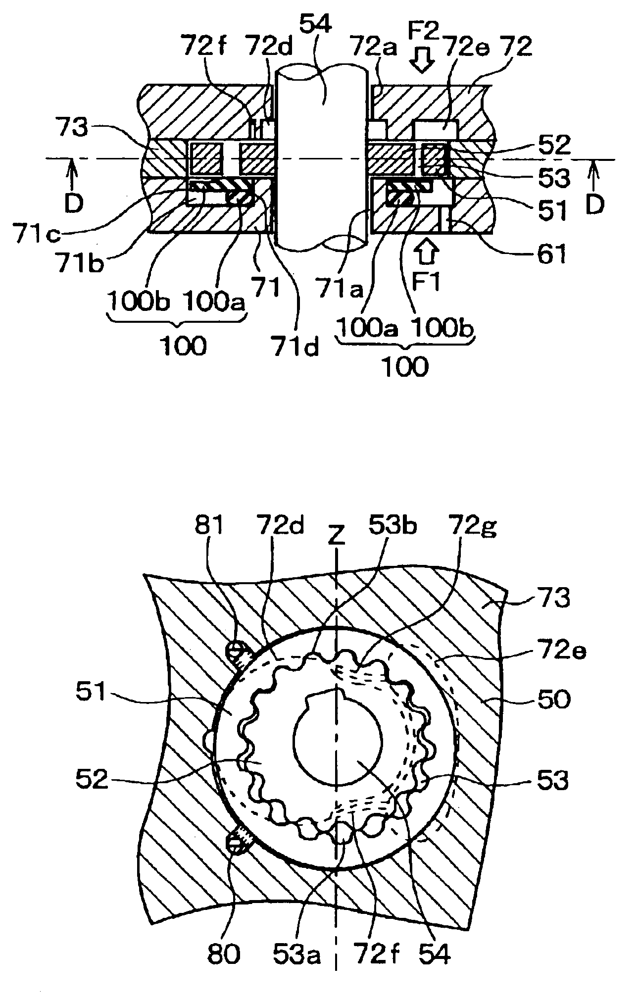
[0112]In the present embodiment, in distinction to the first embodiment, the second side plate 72 is additionally provided with extended trenches 72f and 72g. FIG. 4A is a cross-sectional view of the rotary pump 10 according to the present embodiment; FIG. 4B is a cross-sectional view taken along a line C—C in FIG. 4A; and FIG. 4C is an cross-sectional view taken along a line D—D in FIG. 4B. Structural members that are the same as or equivalent to those of the first embodiment are denoted with the same reference numerals, and their explanation is omitted.
[0113]In the present embodiment the extended trenches 72f and 72g are formed on the axial direction end surface of the second side plate 72. These extended trenches 72f and 72g extend toward the discharge trench 72e from an area that is closer to the side of the central hole 72a than the sealed chambers 53a and 53b.
[0114]A pressing force F1 that presses the rotors 51 and 52 toward the second side plate 72 r...
third embodiment
[0117](Third Embodiment)
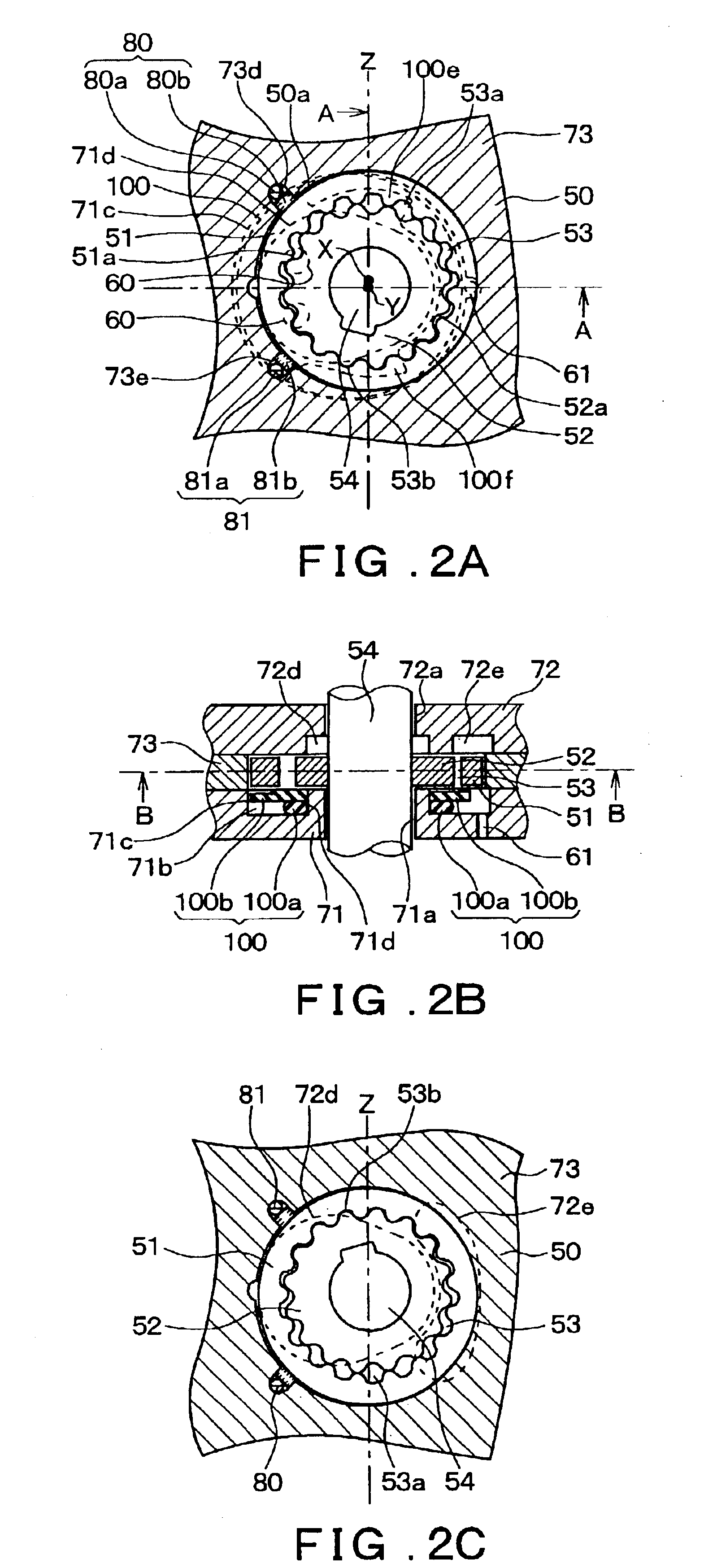
[0118]In the present embodiment the shape of the external periphery side profile of the intake trench 72d of the first embodiment is modified. FIG. 5A is a cross-sectional view of the rotary pump 10 according to the present embodiment; FIG. 5B is a cross-sectional view taken along a line E—E in FIG. 5A; and FIG. 5C is a cross-sectional view taken along a line G—G in FIG. 5B. Structural members that are the same as or equivalent to those of the first embodiment are denoted with the same reference numerals, and their explanation is omitted.
[0119]In the present embodiment the external periphery side profile of the intake trench 72 is offset to the side of the drive shaft 54 in the area that is closer to the side of the central hole 72a than the sealed chambers 53a and 53b. Accordingly, when viewed from the axial direction of the drive shaft 54, the external periphery side profile of the intake trench 72d at the area closer to the central hole 72a than the sealed...
PUM
 Abstract
Description
Claims
Application Information