Method and apparatus for melt-blown fiber encapsulation

Inactive Publication Date: 2005-06-14
OWENS CORNING FIBERGLAS TECH INC
View PDF18 Cites 20 Cited by
  • Summary
  • Abstract
  • Description
  • Claims
  • Application Information

AI Technical Summary

Benefits of technology

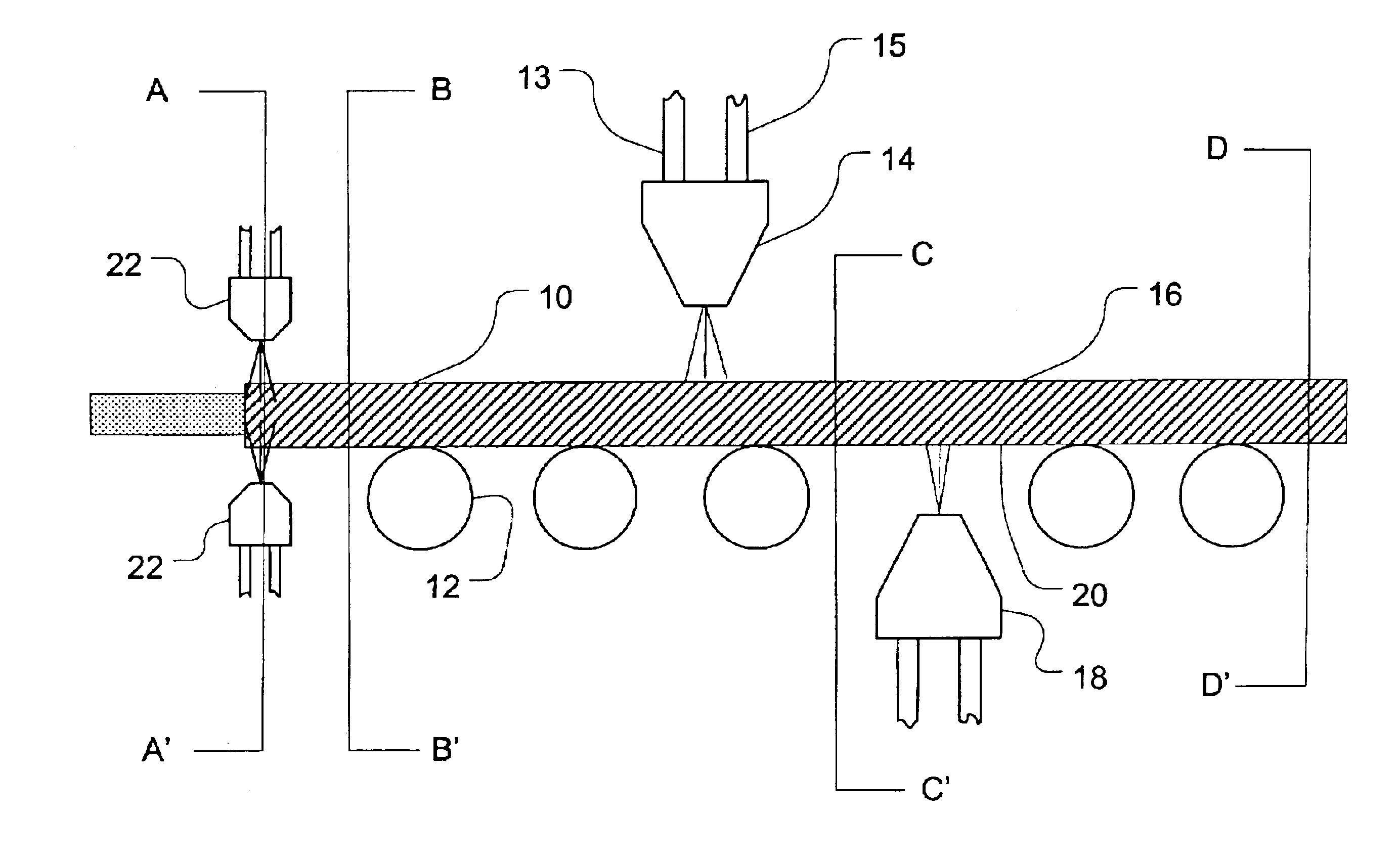
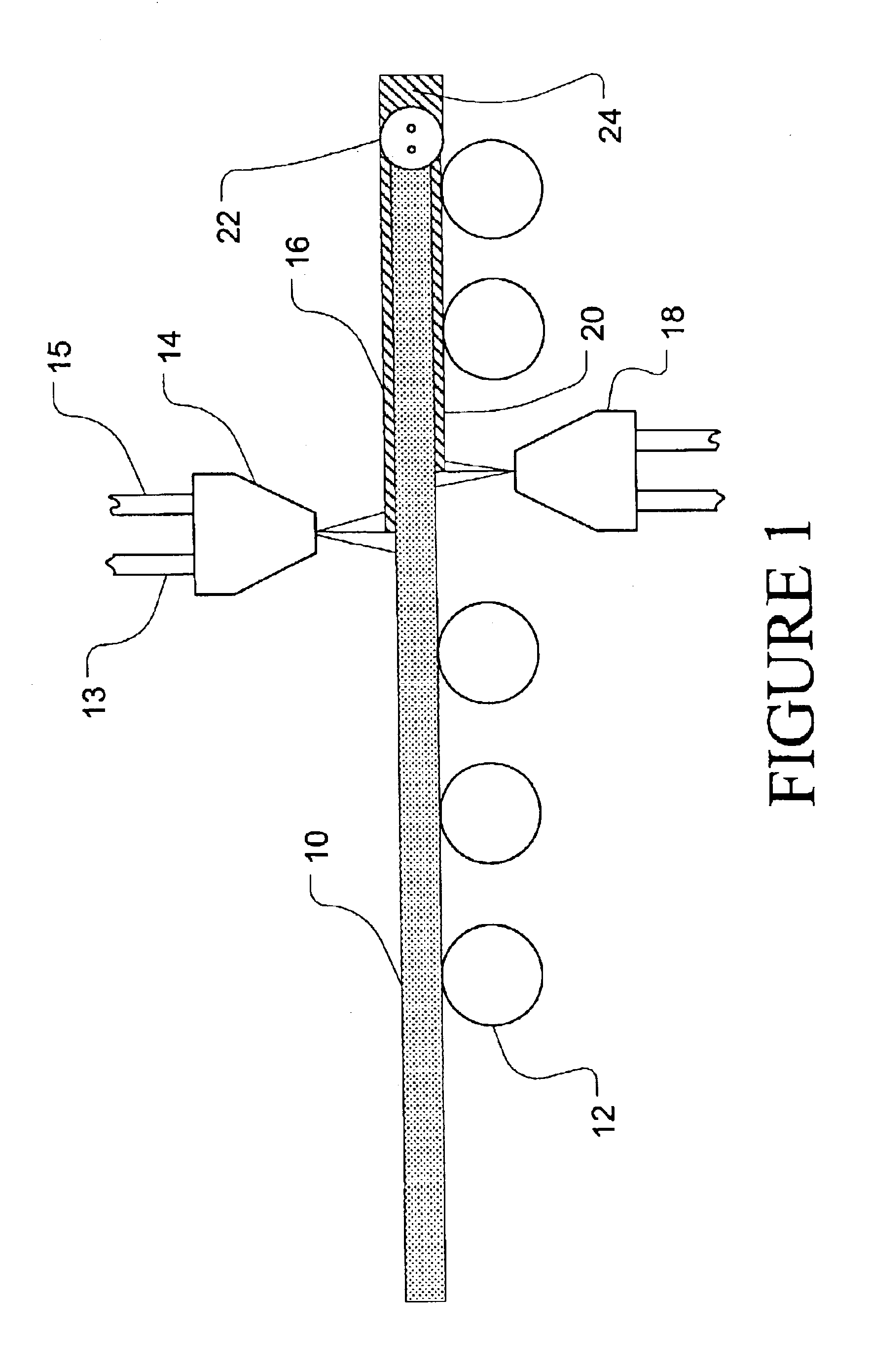
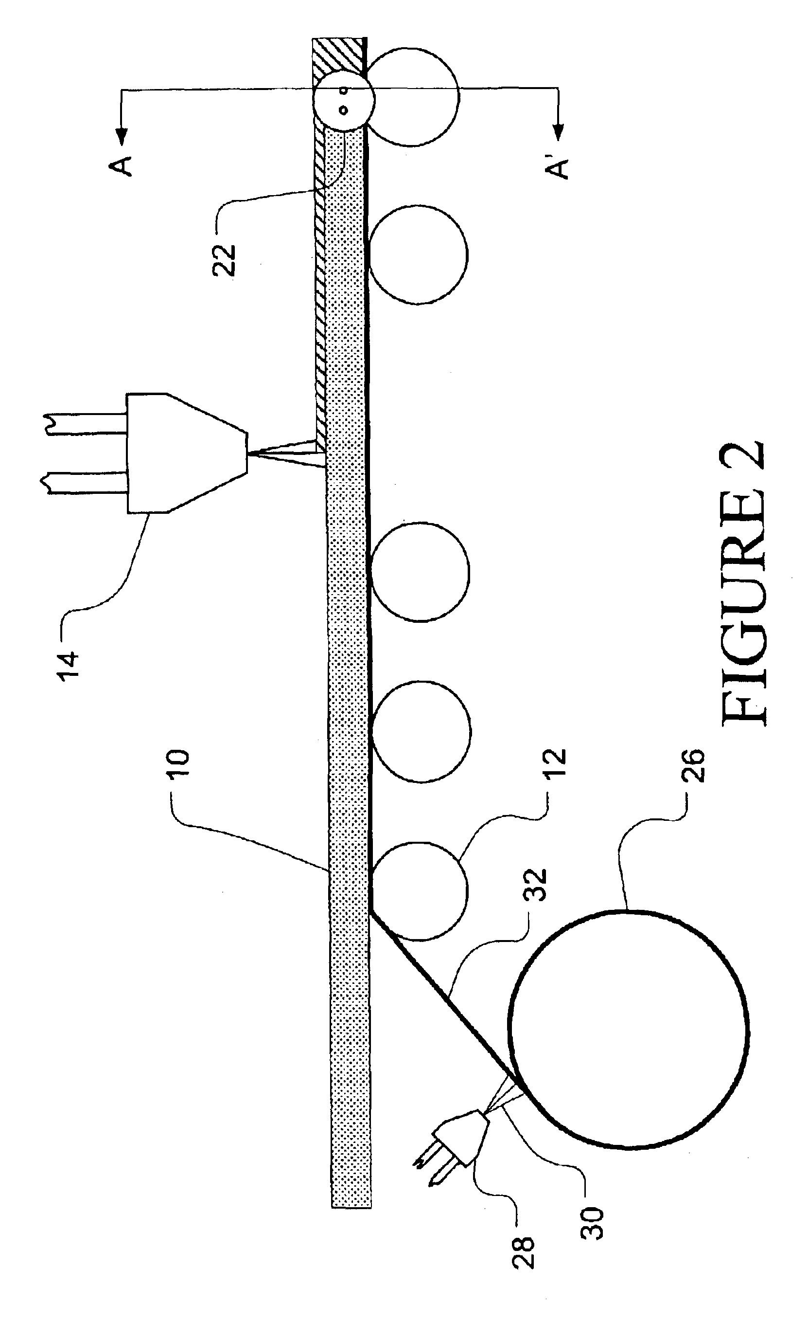
[0013]The invention is directed, in part, to an insulation product comprising an elongated fibrous batt with a polymeric encapsulating layer and, optionally, a vapor barrier layer on one or more surfaces of the fibrous batt. The invention is also, in part, directed to an apparatus for manufacturing an insulation product comprising an elongated fibrous batt with a polymeric encapsulating layer and, optionally, a vapor barrier layer. The invention is also, in part, directed to a method of making an insulation product comprising an elongated fibrous batt with

Problems solved by technology

Such a situation would result in a damp insulation product that cannot perform at its designed efficiency and cause a loss in insulation value (R-Value).
There are, however, some applications that require an insulation product that does not incorporate or provide a vapor barrier, but rather allows water vapor to pass through fairly readily.
Attaching the coextruded film in this manner has some disadvantages in that the particular heating process cannot be abruptly terminated or quickly varied due to the large thermal mass provided by the heated cylinder.
In addition, the heated c

Method used


Image

  • Method and apparatus for melt-blown fiber encapsulation
  • Method and apparatus for melt-blown fiber encapsulation
  • Method and apparatus for melt-blown fiber encapsulation

Examples


example 5

[0043]Twenty-foot (6.1 m) long and 15″ (38 cm) wide R-19 fiber batt was used. The first major surface (top) was coated with melt-blown polypropylene fibers at a rate of about 20 grams / m2 using the same conditions as indicated above for Example 1 and the two minor (side) surfaces were coated with polypropylene fibers sprayed from small hot melt nozzles at a rate of about 20 grams / m2. A vapor retarding layer, specifically a 1.0 mil (25.4 μm) thick polyethylene film, was then bonded to the remaining major surface (bottom) using a pressure sensitive hot melt adhesive (Evans Adhesive Corporation, Columbus, Ohio, product # 07505). The adhesive was applied as 3 continuous stripes, one at center and two along the edges. Each stripe was about 1 inch (2.5 cm) wide, and the glue application rate for each stripe was about 0.2 grams per linear foot (0.65 grams / meter). The resulting product was a faced fiber batt insulation material having a non-woven polypropylene fiber layer on the remaining su...

example 6

[0044]Twenty-foot (6.1 m) long and 15″ (38 cm) wide R-19 batt was used. The two major surfaces (top and bottom) were covered, with a melt blown polypropylene coating applied at a rate of about 20 grams / m2 using the same condition as indicated above for Example 1. The two side surfaces were then spray coated with an EVA polymer (Henkel, product # 80-8330) using small hot melt nozzles. Each of the side surfaces was about 6.5″ (16.5 cm) wide (R19 batt thickness), and the EVA application rate was about 1.3 grams per linear foot for a coating weight of about 2.4 grams / ft2 (25.8 grams / M2). The resulting product was a faced fiber batt insulation material having an encapsulating layer of a non-woven polymeric fibers alternating between regions of polypropylene and EVA, illustrating the ability to “tune” the encapsulating layers on various surfaces to customize the appearance and performance of the resulting insulation product while improving handleability and reducing fiber and dust generat...


PUM

PropertyMeasurementUnit
Lengthaaaaaaaaaa
Densityaaaaaaaaaa
Densityaaaaaaaaaa

Abstract

The invention relates to an insulation product comprising an elongated fibrous batt with at least a partial polymeric encapsulating layer formed by melt-blowing or melt spraying a polymeric composition onto one or more surfaces of the fibrous batt and, optionally, a separate vapor retarding layer applied to one or more surfaces of the fibrous batt and an apparatus for manufacturing such an insulation product.

Description

TECHNICAL FIELD AND INDUSTRIAL APPLICABILITY OF THE INVENTION[0001]This invention relates to fibrous insulation products, and in particular those insulation products of the type suitable for insulating buildings. More specifically, this invention pertains to insulation products having an encapsulating layer and, optionally, a vapor barrier, for improving the handling characteristics and reducing dust and fiber generation in the resulting insulation products.BACKGROUND OF THE INVENTION[0002]Fibrous insulation is typically manufactured by fiberizing a molten composition of polymer or other minerals to form fine fibers and depositing the fibers on a collecting conveyor. Although mineral fibers, such as glass fibers, are typically used in insulation products, depending on the particular application organic fibers, such as polypropylene and polyester may be used singly or in combination with mineral fibers. Most fibrous insulation products also incorporate a binder composition to bond th...

Claims


Application Information

Patent Timeline
IPC IPC(8): E04B1/76E04B1/78D04H13/00
CPCD04H13/002D04H13/008E04B1/78E04B1/7662Y10T428/237Y10T428/239D04H1/559D04H1/56D04H1/72D04H3/16
Inventor DONG, DAOJIE
Owner OWENS CORNING FIBERGLAS TECH INC
Why Eureka
Try Eureka