Delivery system for post-operative power adjustment of adjustable lens

a technology of power adjustment and delivery system, which is applied in the direction of spectales/goggles, instruments, applications, etc., to achieve the effect of convenient use for doctors

Inactive Publication Date: 2005-06-14
RXSIGHT INC
View PDF16 Cites 129 Cited by
  • Summary
  • Abstract
  • Description
  • Claims
  • Application Information

AI Technical Summary

Benefits of technology

[0009]The present invention provides a method and instrument to irradiate a light adjustable lens inside the human eye with an appropriate amount of radiation and a spatially defined intensity pattern. A similar embodiment of the design described here can also be used to irradiate light adjustable lens material for other applications. For example, the invention can be used as an aberration conjugator in correcting other types of optical systems, e.g.: microscopes; telescopes; camera lenses; ex-vivo, custom ordered intraocular lenses (IOLs); and custom ordered contact lenses; and the like. By accurately irradiating the light adjustable lens to correct the patients' vision after implantation, the patient does not have to wear eyeglasses after surgery. Of course, older patients who have lost the ability to accommodate may want to wear some sort of corrective eyewear for near vision. In accordance with embodiments of this invention, following implantation and waiting the necessary time (1 to 4 weeks) for refractive stabilization to occur, aberrations in the eye are measured before, during, and after irradiation. The irradiation source is precisely aligned to the line of sight (LOS) axis of the eye, the intensity and duration of the irradiation are precisely controlled, and the irradiation intensity pattern is controlled and monitored. There is provided a method and instrument that is easy for doctors to use, and which is patient friendly.
[0011]Specific embodiments of the invention provide energy sources for irradiating light adjustable intraocular lenses. Useful sources of irradiation for modifying the light adjustable lens are pulsed UV lasers and arc lamps; and continuous wave (CW) UV sources such as an arc discharge lamp, CW laser, or CW LED. In one embodiment of the invention, an extended ultraviolet light (UV) source is provided, e.g., UV light emitting diodes (LED) for irradiating the lens. The output characteristics of UV LEDs make this source attractive to the present application since they cannot be focused to a tight spot and are limited in total intensity output. Both of these features provide less potential risk to the ocular structures.
[0012]In accordance with another embodiment of the invention, modifying light is generated and projected onto the light adjustable lens in a pattern that compensates for the aberration, for example, one that is opposite in phase to the measured aberrations. In a particular form of this embodiment, a UV vertical-cavity surface-emitting laser (VCSEL) array is used to generate a UV intensity pattern and project it onto the surface of a light adjustable lens. Such an arrangement provides advantages in that the optical system is smaller, lighter, more versatile in generating different irradiation intensity patterns, and less complicated than other UV patterning systems. The optical efficiency is higher than other systems, producing less heat; and the operating lifetime of the source is longer.
[0014]Once the light adjustable lens is modified to the desired extent, the optical properties of the lens are photolocked by irradiating the entire lens with light of the appropriate wavelength to equally and completely photopolymerize any refraction modulating composition remaining in the in the light adjustable lens, i.e. effectively remove the driving force for refractive change.

Problems solved by technology

The output characteristics of UV LEDs make this source attractive to the present application since they cannot be focused to a tight spot and are limited in total intensity output.

Method used


Image

  • Delivery system for post-operative power adjustment of adjustable lens
  • Delivery system for post-operative power adjustment of adjustable lens
  • Delivery system for post-operative power adjustment of adjustable lens

Examples


Embodiment Construction

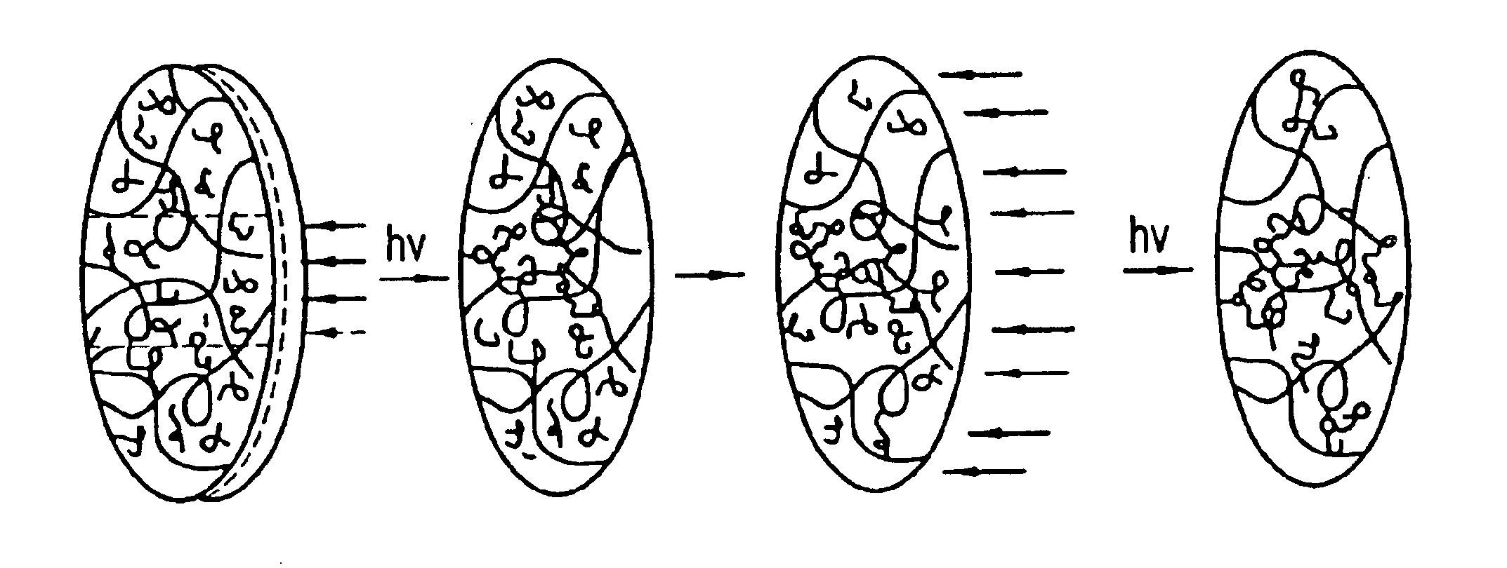
[0032]Generally, a light adjustable lens comprises a first polymer matrix and a refraction modulating composition dispersed therein. The first polymer matrix forms the optical element framework and is generally responsible for many of its material properties. The refraction modulating composition may be a single compound or a combination of compounds that is capable of stimulus-induced polymerization, preferably photo-polymerization. As used herein, the term “polymerization” refers to a reaction wherein at least one of the components of the refraction modulating composition reacts to form at least one covalent or physical bond with either a like component or with a different component. The identities of the first polymer matrix and the refraction modulating compositions will depend on the end use of the optical element. However, as a general rule, the first polymer matrix and the refraction modulating composition are selected such that the components that comprise the refraction mod...


PUM

PropertyMeasurementUnit
poweraaaaaaaaaa
wavelengthaaaaaaaaaa
wavelengthsaaaaaaaaaa

Abstract

A method and instrument to irradiate a light adjustable lens, for example, inside a human eye, with an appropriate amount of radiation in an appropriate intensity pattern by first measuring aberrations in the optical system containing the lens; aligning a source of the modifying radiation so as to impinge the radiation onto the lens in a pattern that will null the aberrations. The quantity of the impinging radiation is controlled by controlling the intensity and duration of the irradiation. The pattern is controlled and monitored while the lens is irradiated.

Description

CROSS REFERENCE TO RELATED APPLICATIONS[0001]This application is based on U.S. Application Ser. Nos. 60 / 235,457, filed Sep. 26, 2000; 60 / 235,454 filed Sep. 26, 2000; and 60 / 269,151, filed Feb. 15, 2001.BACKGROUND OF THE INVENTION[0002]1. Field of the Invention[0003]This invention relates generally to the post-manufacture alteration of the properties of an optical device, and, more specifically, to the irradiation of light adjustable lenses.[0004]2. Background Information[0005]Cataract surgery procedures involve making an incision in the anterior lens capsule to remove the cataractous crystalline lens and implanting an intraocular lens (IOL) in its place. In general, there are two types of intraocular lenses. One type replaces the eye's natural lens, usually to replace a cataractous lens. The other type is used to supplement an existing lens and functions as a permanent corrective lens. This type of lens (referred to as a phakic IOL) is implanted in the anterior or posterior chamber ...

Claims


Application Information

Patent Timeline
Patent Type & Authority Patents(United States)
IPC IPC(8): A61B3/103A61F9/00A61F9/008A61F9/007G02C7/04A61B3/10A61F2/16G02B3/00
CPCA61F2/1627A61F2/1635A61F9/008A61F9/00812G02C7/04A61F9/0017A61F9/00806G02C2202/14A61F2009/00846A61F2009/00848A61F2009/00859A61F2009/0087A61F2009/00887A61F9/00817A61F2/1637A61F2/1659
Inventor PLATT, BEN C.SANDSTEDT, CHRISTIAN A.EBEL, JAMES A.
Owner RXSIGHT INC
Why Eureka
Try Eureka