Methods of producing synthetic resin wire
- Summary
- Abstract
- Description
- Claims
- Application Information
AI Technical Summary
Benefits of technology
Problems solved by technology
Method used
Image

Examples
embodiment 1
(Embodiment 1)
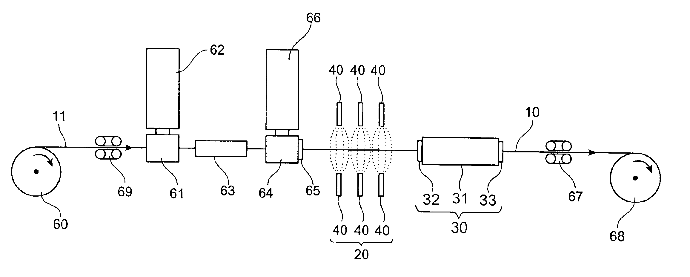
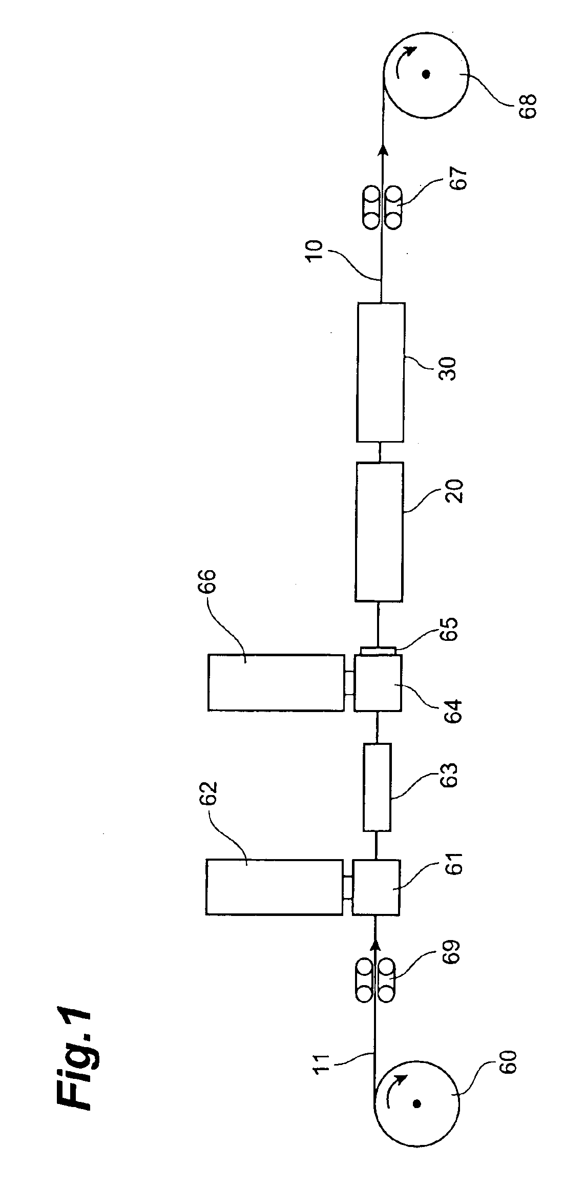
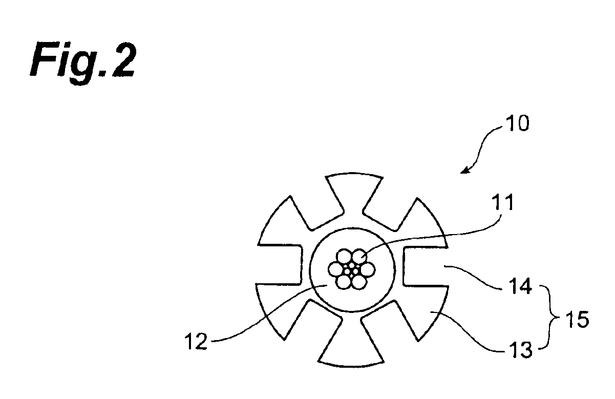
[0045]FIG. 1 is a schematic overall diagram showing a system for production of the synthetic resin rod according to Embodiment 1. FIG. 2 is a cross-sectional view of a synthetic resin rod, and the synthetic resin rod 10 has such structure that a primary coating layer 12 of an adhesive resin A is provided around the periphery of tension-resistive wire 11 and that the periphery of the layer 12 is coated with a spacer 15 made of a synthetic resin B and having six grooves 14 in the longitudinal direction on its periphery. The grooves 14 can be either “helical grooves” formed by ribs 13 which are helical in one direction or “SZ grooves” formed by ribs 13 which change their turning directions at regular intervals.
[0046]In the production system shown in FIG. 1, the tension-resistive wire 11 fed out of a wire feeder 60 is guided via brake capstan 69, through a first crosshead 61 of first extruder 62, and through a first water tank 63 disposed in the extruding direction of the ...
embodiment 2
(Embodiment 2)
[0055]FIG. 5 is a schematic overall view showing a system for production of the synthetic resin rod according to Embodiment 2. In FIG. 5, the tension-resistive wire 11 fed out of the wire feeder 60 is guided via the brake capstan 69, through the first crosshead 61 of the first extruder 62, and through the first water tank 63 disposed in the extruding direction of the first crosshead 61 to be provided with the first coating layer 12 of the adhesive resin around the tension-resistive wire 11, and subsequently, the tension-resistive wire 11 provided with the first coating layer 12 is guided through the second crosshead 64 of the second extruder 66 having the rotary die 65 to extrude the spacer 15 having the grooves 14, thus forming the synthetic resin rod 10 (extruding step). Then the extruded rod 10 is guided through mist spray devices 40 as the pre-cooling means (second cooling means) 20 and through the cooling device provided with the water tank 31 as the main cooling ...
embodiment 3
(Embodiment 3)
[0062]FIG. 7 is a schematic overall view showing a system for production of the synthetic resin rod according to Embodiment 3. In FIG. 7, the tension-resistive wire 11 fed out of the wire feeder 60 is guided via the brake capstan 69, through the first crosshead 61 of the first extruder 62, and through the first water tank 63 disposed in the extruding direction of the first crosshead 61 to be provided with the first coating layer 12 of the adhesive resin around the tension-resistive wire 11, and subsequently, the tension-resistive wire 11 provided with the first coating layer 12 is guided through the second crosshead 64 of the second extruder 66 having the rotary die 65 to extrude the spacer 15 having the helical or SZ grooves 14, thus forming the synthetic resin rod 10 (extruding step). Then the extruded rod 10 is guided through air spray devices 21 and mist spray devices 40 as the pre-cooling means (second cooling means) 20 and through the cooling device provided with...
PUM
| Property | Measurement | Unit |
|---|---|---|
| Particle size | aaaaa | aaaaa |
| Temperature | aaaaa | aaaaa |
| Temperature | aaaaa | aaaaa |
Abstract
Description
Claims
Application Information
 - R&D
- Intellectual Property
- Life Sciences
- Materials
- Tech Scout
- Unparalleled Data Quality
- Higher Quality Content
- 60% Fewer Hallucinations
Browse by: Latest US Patents, China's latest patents, Technical Efficacy Thesaurus, Application Domain, Technology Topic, Popular Technical Reports.
© 2025 PatSnap. All rights reserved.Legal|Privacy policy|Modern Slavery Act Transparency Statement|Sitemap|About US| Contact US: help@patsnap.com