Current-perpendicular-to-plane-type magnetoresistive device, and magnetic head and magnetic recording-reproducing apparatus using the same

a technology of magnetic resonance and perpendicular to the plane, which is applied in the direction of nanoinformatics, magnetic bodies, instruments, etc., can solve the problem of low resistance itself and achieve the effect of increasing the resistance chang

Inactive Publication Date: 2005-06-14
KK TOSHIBA
View PDF14 Cites 67 Cited by
  • Summary
  • Abstract
  • Description
  • Claims
  • Application Information

AI Technical Summary

Benefits of technology

[0011]An object of the present invention is to increase change in the resistance by arranging an appropriate material in at least one

Problems solved by technology

However, the artificial lattice film requires a high magnetic field for saturating the magnetization and, thus, is not adapted for use as a film material for the MR head.
However, in the spin valve structure, the total thickness of the

Method used


Image

  • Current-perpendicular-to-plane-type magnetoresistive device, and magnetic head and magnetic recording-reproducing apparatus using the same
  • Current-perpendicular-to-plane-type magnetoresistive device, and magnetic head and magnetic recording-reproducing apparatus using the same
  • Current-perpendicular-to-plane-type magnetoresistive device, and magnetic head and magnetic recording-reproducing apparatus using the same

Examples


first embodiment

[0083](First Embodiment)

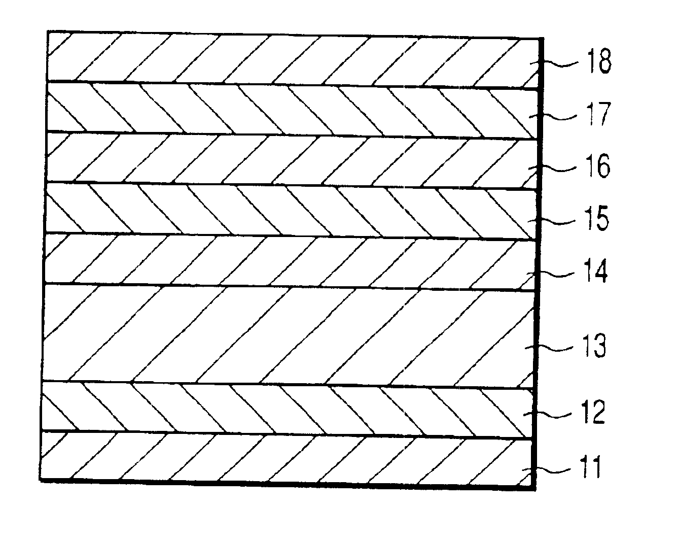
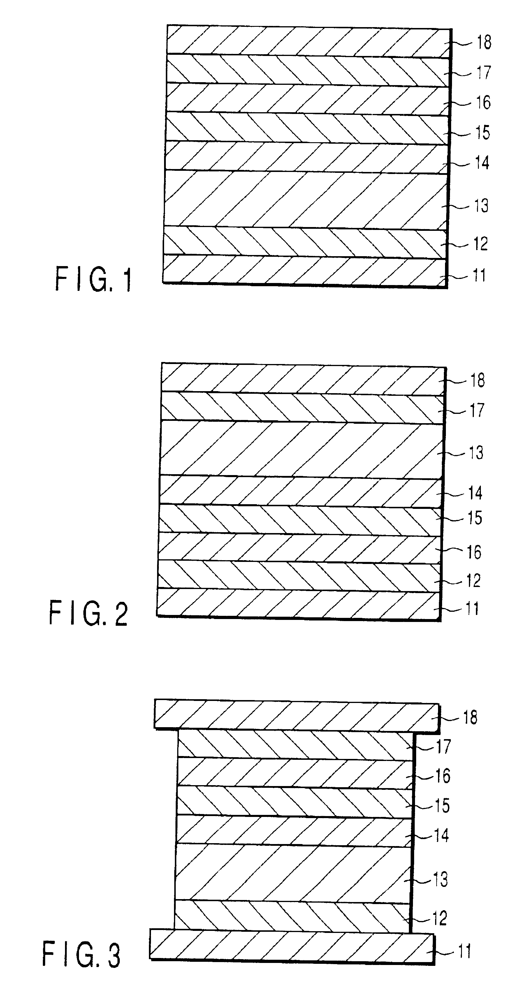
[0084]Manufactured were magnetoresistive films including a magnetization pinned layer and a magnetization free layer each formed of a Co100-xFex alloy having a varied Fe concentration. The film configuration was as follows: lower electrode / 5 nm-Ta / 5 nm-NiFeCr / 15 nm-PtMn (antiferromagnetic layer) / 7 nm-Co100-xFex (pinned layer) / 7 nm-Cu (nonmagnetic intermediate layer) / 7 nm-Co100-xFex (free layer) / 10 nm-Ta / upper electrode, where the numerals represent the thickness of each film.

[0085]The Fe concentration x was changed to 0, 10 atomic %, 20 atomic %, 27 atomic %, 30 atomic %, 40 atomic %, 50 atomic %, 60 atomic %, 70 atomic %, 80 atomic %, 90 atomic % and 100 atomic %, with the thickness of each of the free layer and the pinned layer fixed to 7 nm.

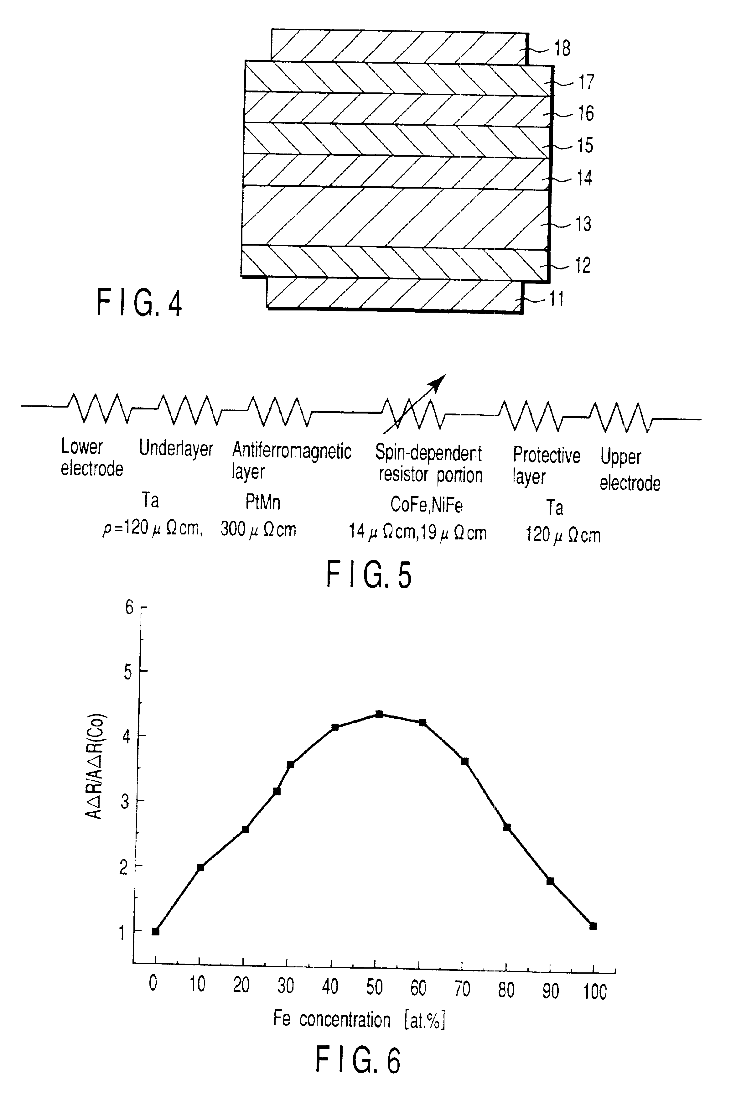
[0086]FIG. 6 is a graph showing the relationship between resistance change and Fe concentration. The resistance change AΔR per one μm2 of device area, which is normalized with the resistance change AΔR (0.5 mΩμm2) of th...

second embodiment

[0088](Second Embodiment)

[0089]Manufactured were magnetoresistive films including a magnetization pinned layer and a magnetization free layer each formed of a Ni100-xFex alloy having a varied Fe concentration. The film configuration was as follows: lower electrode / 5 nm-Ta / 5 nm-NiFeCr / 15 nm-PtMn / 7 nm-Ni100-xFex / 7 nm-Cu / 7 nm-Ni100-xFex / 10 nm-Ta / upper electrode, where the numerals represent the thickness of each film.

[0090]The Fe concentration x was changed to 0, 10 atomic %, 20 atomic %, 30 atomic %, 40 atomic %, 50 atomic %, 60 atomic %, 70 atomic %, 80 atomic %, 90 atomic % and 100 atomic %, with the thickness of each of the magnetization free layer and the magnetization pinned layer fixed to 7 nm.

[0091]FIG. 7 is a graph showing the relationship between resistance change and Fe concentration. The resistance change AΔR per one μm2 of device area, which is normalized with the resistance change AΔR (0.5 mΩμm2) of the device including a free layer and a pinned layer each formed of a pur...

third embodiment

[0093](Third Embodiment)

[0094]Manufactured were magnetoresistive films including a magnetization pinned layer and a magnetization free layer each formed of a Ni100-xCox alloy having a varied Co concentration. The film configuration was as follows: lower electrode / 5 nm-Ta / 5 nm-NiFeCr / 15 nm-PtMn / 7 nm-Ni100-xCox / 7 nm-Cu / 7 nm-Ni100-xCox / 10 nm-Ta / upper electrode, where the numerals represent the thickness of each film.

[0095]The Co concentration x was changed to 0, 10 atomic %, 20 atomic %, 30 atomic %, 40 atomic %, 50 atomic %, 60 atomic %, 70 atomic %, 80 atomic %, 90 atomic % and 100 atomic %, with the thickness of each of the magnetization free layer and the magnetization pinned layer fixed to 7 nm.

[0096]FIG. 8 is a graph showing a relationship between resistance change and Co concentration. The resistance change AΔR per one μm2 of device area, which is normalized with the resistance change AΔR (0.5 mΩμm2) of the device including a free layer and a pinned layer each formed of a pure C...


PUM

PropertyMeasurementUnit
Fractionaaaaaaaaaa
Thicknessaaaaaaaaaa
Thicknessaaaaaaaaaa

Abstract

A magnetoresistive device includes a magnetization pinned layer, a magnetization free layer, a nonmagnetic intermediate layer formed between the magnetization pinned layer and the magnetization free layer, and electrodes allowing a sense current to flow in a direction substantially perpendicular to the plane of the stack including the magnetization pinned layer, the nonmagnetic intermediate layer and the magnetization free layer. At least one of the magnetization pinned layer and the magnetization free layer is substantially formed of a binary or ternary alloy represented by the formula FeaCobNic (where a+b+c=100 at %, and a≦75 at %, b≦75 at %, and c≦63 at %), or formed of an alloy having a body-centered cubic crystal structure.

Description

CROSS-REFERENCE TO RELATED APPLICATIONS[0001]This application is based upon and claims the benefit of priority from the prior Japanese Patent Applications No. 2001-025736, filed Feb. 1, 2001; and No. 2001-246613, filed Aug. 15, 2001, the entire contents of both of which are incorporated herein by reference.BACKGROUND OF THE INVENTION[0002]1. Field of the Invention[0003]The present invention relates to a magneto-resistive device in which a sense current is allowed to flow in a direction perpendicular to film plane for detecting an external magnetic field as well as to a magnetic head and a magnetic recording-reproducing apparatus.[0004]2. Description of the Related Art[0005]Conventionally, read-out of information recorded in a magnetic recording medium has been performed with a reproduce magnetic head including a coil, which is moved relative to the recording medium so as to detect a voltage induced in the coil by electromagnetic induction. Then, a magnetoresistive device (hereinafte...

Claims


Application Information

Patent Timeline
IPC IPC(8): H01F10/00G11B5/39H01F10/32G11B5/012H01L43/10
CPCB82Y10/00G01R33/093G11B5/3903G11B5/3906G11C11/16H01F10/324H01F10/3268H01L43/10B82Y25/00Y10T428/1129G11B5/012Y10T428/1143Y10T428/12951Y10T428/12917Y10T428/12868Y10T428/1121Y10T428/115Y10T428/1193Y10T428/265Y10T428/32Y10T428/12465Y10T428/1107Y10T428/1171G11C11/161H10N50/85
Inventor YUASA, HIROMIYOSHIKAWA, MASATOSHIKAMIGUCHI, YUZOIWASAKI, HITOSHISAHASHI, MASASHI
Owner KK TOSHIBA
Why Eureka
Try Eureka