Rotating asynchronous converter and a generator device

a generator device and asynchronous converter technology, applied in the direction of magnetic circuits, emergency protective arrangements for automatic disconnection, insulated cables, etc., can solve the problems of low efficiency (ca 95%), use of special converter transformers with very complex design, and drawbacks of static converters. achieve the effect of high efficiency

Inactive Publication Date: 2005-06-14
ABB (SCHWEIZ) AG
View PDF750 Cites 19 Cited by
  • Summary
  • Abstract
  • Description
  • Claims
  • Application Information

AI Technical Summary

Benefits of technology

[0016]A very important advantage of the present invention is that it is possible to achieve a connection of two not synchronous networks without the further use of transformers or any other equipment. Another advantage is the high efficiency, which is expected to be 99%.
[0017]By designing the insulation system, which suitably is solid, so that it in thermal and electrical view is dimensioned for voltages exceeding 36 kV, the system can be connected to high voltage power networks without the use of intermediate step-down-transformers, whereby is achieved the above referenced advantages. Such a system is preferably, but not necessarily, designed in such a way that it comprises the features of the rotating asynchronous converter.
[0018]Another object of the invention is to solve the above mentioned problems and to provide a generator device with variable rotational speed. This object is achieved by providing a generator device.
[0019]Accordingly, the generator device comprises a stator connected to an AC network with a frequency f2, a first cylindrical rotor connected to a turbine, which rotates with a frequency f1. The generator device also comprises a rotor means which rotates in dependence of the frequencies f1, f2. The stator and the first cylindrical rotor each comprises at least one winding, wherein each winding comprises at least one current-carrying conductor, and each winding comprises an insulation system, which comprises on the one hand at least two semiconducting layers, wherein each layer constitutes substantially an equipotential surface, and on the other hand between them is arranged a solid insulation.
[0020]According to another embodiment of the generator device, it comprises a stator connected to an AC network with a frequency f2, and a first cylindrical rotor connected to a turbine, which rotates with a frequency f1. The generator device also comprises a rotor means which rotates in dependence of the frequencies f1, f2. The stator and the first cylindrical rotor each comprises at least one winding, wherein each winding comprises a cable comprising at least one current-carrying conductor, each conductor comprises a number of strands, around said conductor is arranged an inner semiconducting layer, around said inner semiconducting layer is arranged an insulating layer of solid insulation, and around said insulating layer is arranged an outer semiconducting layer.
[0021]The above mentioned and other preferable embodiments of the present invention are specified in the dependent claims.

Problems solved by technology

Static converters have drawbacks such as relatively low efficiency (ca 95%) owing to the losses in the semiconductors, harmonics which have to be compensated with the aid of filters.
The use of DC intermediate links leads to the use of special converter transformers with very complex design.
The fillers are leading to a great need of space for the total assembly.

Method used


Image

  • Rotating asynchronous converter and a generator device
  • Rotating asynchronous converter and a generator device
  • Rotating asynchronous converter and a generator device

Examples


first embodiment

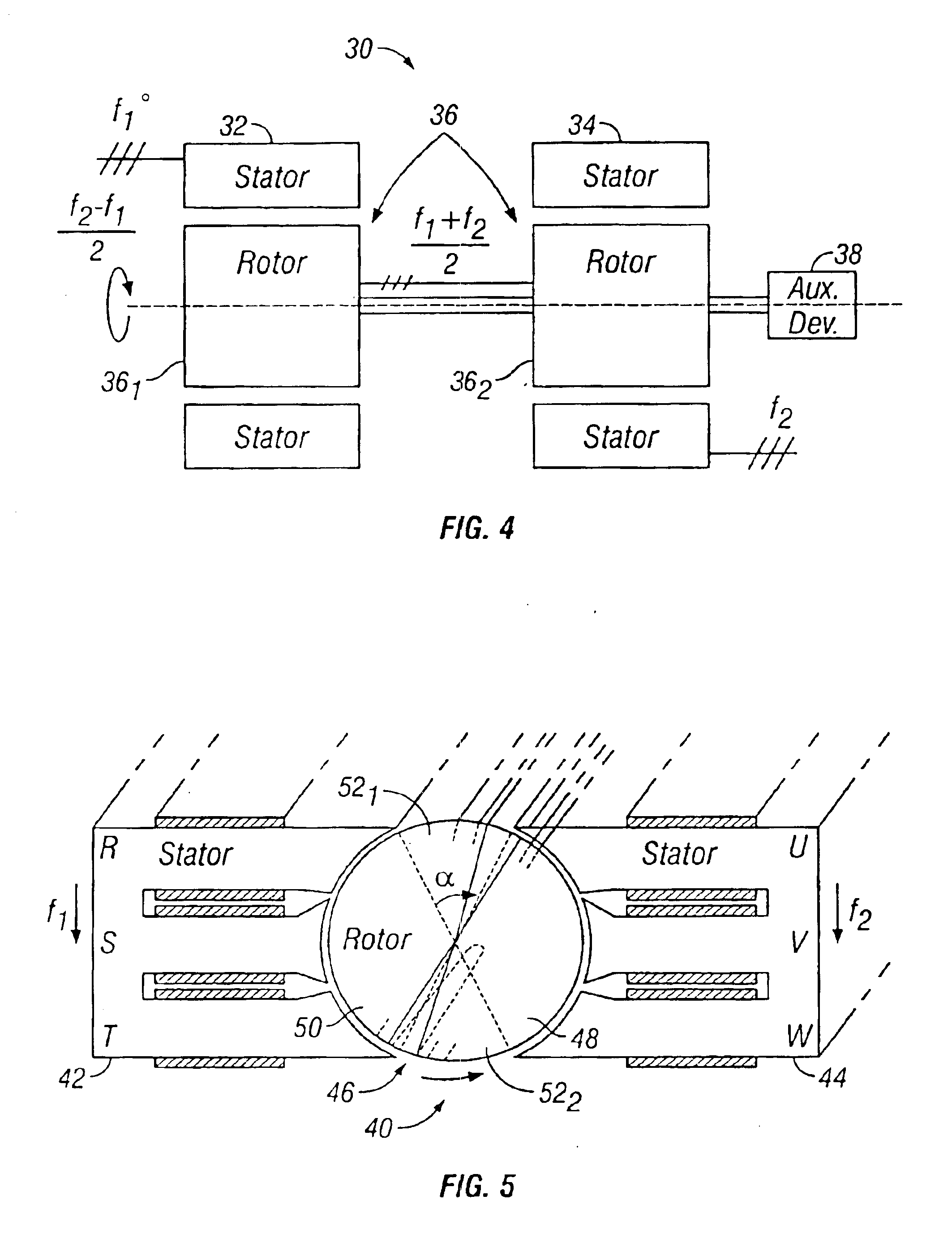
[0033]FIG. 4 shows a rotating asynchronous converter 30 according to the present invention. The rotating asynchronous converter 30 is used for connection of AC networks with equal or different frequencies. The converter 30 comprises a first stator 32 connected to a first AC network (not disclosed) with a first frequency f1, and a second stator 34 connected to a second AC network (not disclosed) with a second frequency f2. In the disclosed embodiment the stators 32, 34 are three phase stators 32, 34 comprising three windings each, wherein each winding comprises at least one current-carrying conductor, and each winding comprises an insulation system, which comprises on the one hand at least two semiconducting layers, wherein each layer constitutes substantially an equipotential surface, and on the other hand between them is arranged a solid insulation. The windings can also be formed of a cable of the type disclosed in FIG. 3. The converter 30 also comprises a rotor means 36 which rot...

second embodiment

[0034]In FIG. 5 there is disclosed the rotating asynchronous converter 40 according to the present invention. The rotating asynchronous converter 40 is also used for connection of AC networks with equal or different frequencies. The converter 40 comprises a first stator 42 connected to a first AC network (not disclosed) with a first frequency f1, and a second stator 44 connected to a second AC network (not disclosed) with a second frequency f2. In the disclosed embodiment the stators 42, 44 are three phase stators 42, 44 comprising three windings each, wherein each winding can be of the type described in connection to FIG. 4. The converter 40 also comprises a rotor means 46 which rotates in dependence of the first and second frequencies f1, f2. In the disclosed embodiment the rotor means 46 comprises only one rotor 46 concentrically arranged in respect of said stators 42, 44. Said rotor 46 also comprises a first loop of wire 48 and a second loop of wire 50, wherein said loops of wir...


PUM

PropertyMeasurementUnit
diameteraaaaaaaaaa
frequencyaaaaaaaaaa
voltagesaaaaaaaaaa

Abstract

A rotating asynchronous converter for connection of AC network with equal or different frequencies employs a first stator connected to a first AC network with a first frequency and a second stator connected to a second AC network with a second frequency, and a rotor which rotates in response to the first and second frequencies. The converter has at least one winding formed of a cable, including a conductor and a magnetically permeable, electric field confining insulating covering surrounding the conductor.

Description

TECHNICAL FIELD OF THE INVENTION[0001]The present invention relates to a rotating asynchronous converter.[0002]The present invention also relates to a generator device.BACKGROUND OF THE INVENTION[0003]In a number of situations exchange of power must be performed between AC networks with different or at least not synchronous frequencies. The most frequent cases are the following:[0004]1. Connection of not synchronous three phase networks with equal rating frequencies, e.g. between eastern and western Europe.[0005]2. Connection of three phase networks with different frequencies, most usually 50 Hz / 60 Hz (e.g. Japan, Latin America).[0006]3. Connection of a three phase network and a low frequency, one / two phase network for railway supply, in Europe 50 Hz / 16.2 / 3 Hz, in USA 60 Hz / 25 Hz.[0007]4. The use of rotating asynchronous converters as a series compensation in long distance AC transmission.[0008]Today, the connection is performed with the aid of power electronics and DC intermediate ...

Claims


Application Information

Patent Timeline
Patent Type & Authority Patents(United States)
IPC IPC(8): H01F27/32H01F3/14H01F3/00H01F3/10H01F27/28H01F27/34H02K3/40H02K3/48H02K3/14H02K3/12H02K3/28H02K15/00H02K11/04H02K15/12H02K3/32H02K1/16H02K9/19H02M7/04B60M3/00H01B7/00H01B7/02H01F27/00H01F29/14H02H3/02H02J3/36H02K15/085H02K47/18H02M3/00
CPCH01F3/10H01F27/288H01F27/323H01F27/34H02K3/14H02K3/28H02K3/40H02K3/48H02K11/048H02K15/00H02K15/12H01F3/14Y10S174/19H01F2027/2833H01F2027/329H01F2029/143H02K1/165H02K9/19H02K2203/15Y10S174/29Y10S174/20Y10S174/22Y10S174/15Y10S174/28Y10S174/17H01F29/14H02H3/025Y10S174/24Y10S174/13Y10S174/14Y10S174/26Y10S174/25H02K11/05B60M3/00H01B7/02
Inventor LEIJON, MATSSCHUTTE, THORSTENSASSE, CHRISTIANFROMM, UDO
Owner ABB (SCHWEIZ) AG
Why Eureka
Try Eureka