Vehicular sound-processing system incorporating an interior mirror user-interaction site for a restricted-range wireless communication system
Inactive Publication Date: 2005-06-14
DONNELLY CORP
View PDF99 Cites 237 Cited by
Summary
Abstract
Description
Claims
Application Information
AI Technical Summary
This helps you quickly interpret patents by identifying the three key elements:
Problems solved by technology
Method used
Benefits of technology
[0015]Accordingly, the present invention provides an indicator for a microphone or accessory module for use with an audio system, such as a hands-free cellular telephone, audio recording device, emergency communication device or the like. The indicator provides a signal to a user of the audio system which communicates whether a human vocal audio signal being received by the audio system is above a threshold level and/or is at least substantially discriminated from other audible noise, so that the vocal signal to non-vocal audible signals received by the audio system from the microphone exceeds a predetermined threshold ratio. Preferably, this ratio is at least 2:1. Most preferably, this ratio is at least 10:1. The microphone and indicator may be mounted in the vehicle cabin, and preferably is mounted as part of the interior rearview mirror system. The accessory module may contain the microphone and/or the indicator and is preferably mounted above the mirror between the mirror and the headliner of the vehicle, which provides a fixed location of the microphone for maintaining proper orientation of the microphone with respect to the vehicle interior. The indicator may be mounted at the accessory module, a rearview mirror housing, behind the mirror reflector in the housing so as to illuminate through the reflector, a rearview mirror mounting portion or a headliner of the vehicle. Because the accessory module is a separate component from the mirror and headliner, additional mirror or headliner console components for mounting the microphone are not required. The present invention facilitates fewer parts in the assembly plant since the headliner and mirror assem
Problems solved by technology
Lack of clarity and/or volume and/or the presence of noise may lead to an incorrect select
Method used
Image
Click on the blue label to locate the original text in one second.
Reading with bidirectional positioning of images and text.
Examples
Embodiment Construction
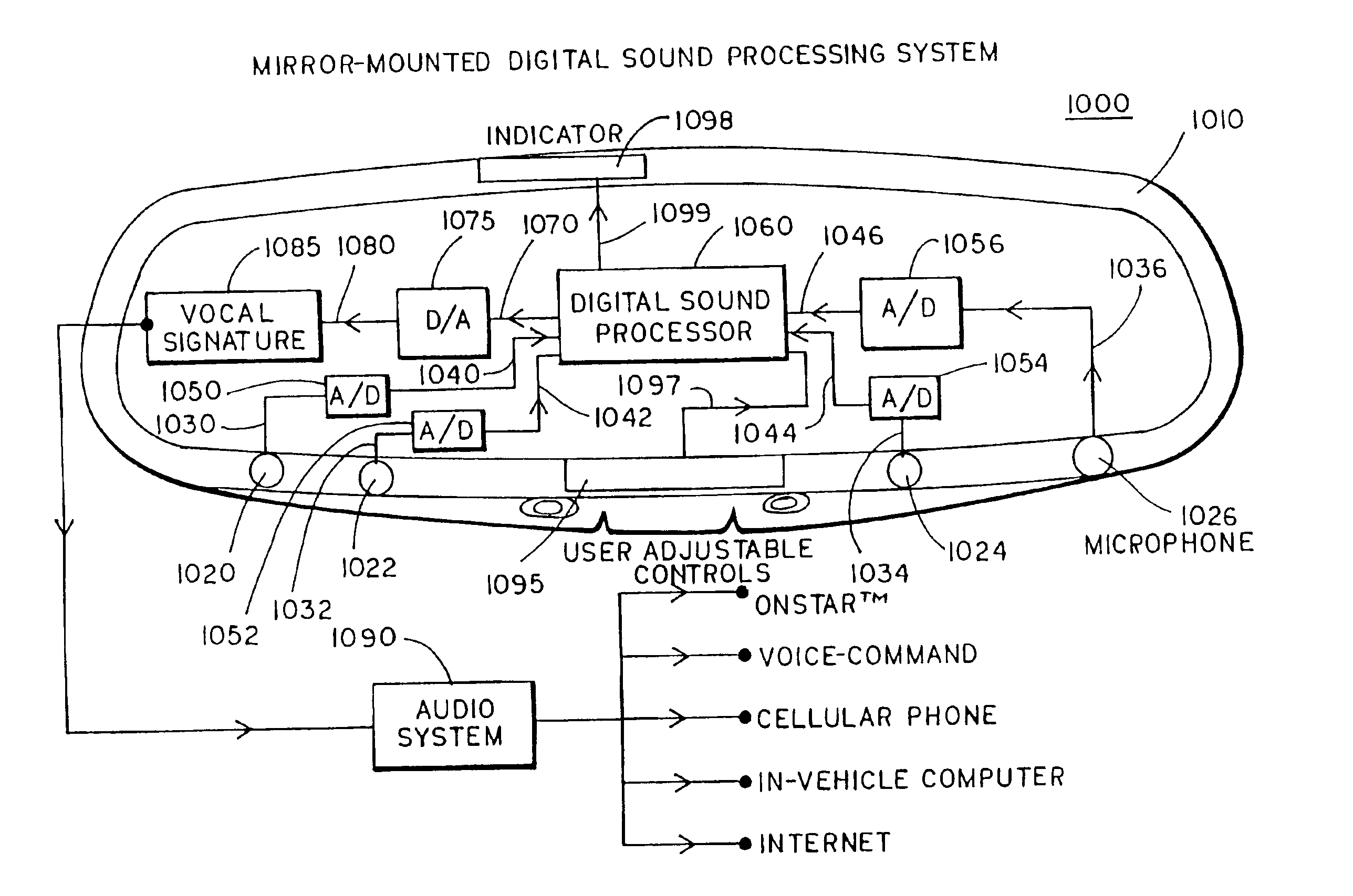
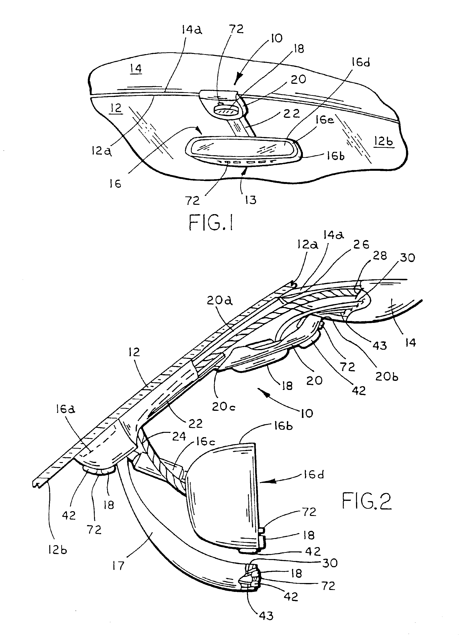
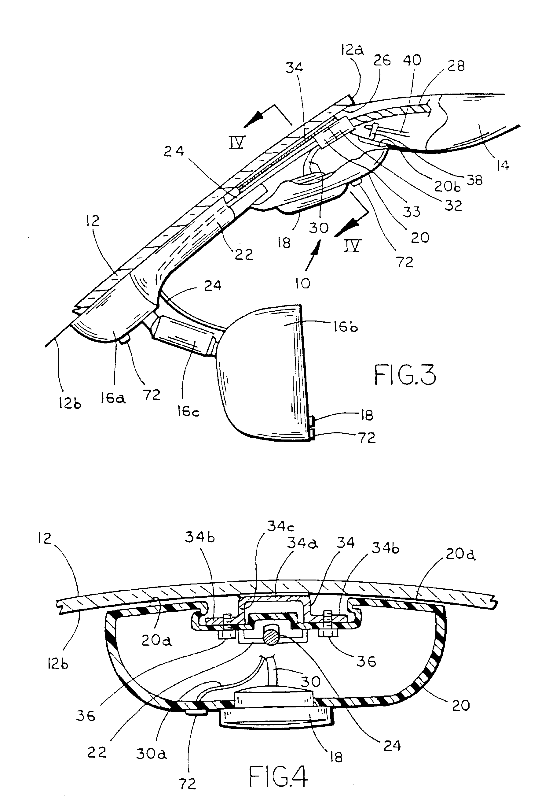
[0035]Referring now specifically to the drawings, and the illustrative embodiments depicted therein, an accessory or microphone module 10 is mounted adjacent to a vehicle windshield 12, as shown in FIG. 1. Microphone module 10 may be implemented in the vehicle in association with an audio system, such as a cellular telephone, a recording device, such as a dictation system, an emergency communication device, such as the ONSTAR™ system commercially available in certain General Motors vehicles, or any other audio device which may include a microphone or audio receiving device. Preferably, the manually actuated buttons to operate the ONSTAR™ system are mounted at a movable housing 16b of an interior rear view mirror assembly 16, such as is shown generally at 13 in FIG. 1. The vehicle includes a headliner 14, which at least partially covers the ceiling of an interior passenger compartment of the vehicle and has a forward edge 14a which interfaces with an upper edge 12a of windshield 12. ...
PUM
Abstract
The interior cabin of a vehicle is provided with a vehicular sound-processing system that comprises an interior rearview mirror assembly, the mirror assembly including a mirror housing and a reflective element. An accessory is located in the interior cabin. The interior rearview mirror assembly comprises a user-interaction site for a wireless communication system, the wireless communication system communicating with the accessory. The user-interaction site comprises at least one microphone for producing an audio output in response to detection of vocal input of a human speaker in the interior cabin with the vehicle cabin noise superimposed thereon. Preferably, the user-interaction site further comprises at least one manually operated control input. The restricted-range wireless communication system preferably comprises one of a radio frequency restricted-range wireless communication system and an infrared restricted-range wireless communication system. Signals indicative of the vocal input detected at the user-interaction site of the interior mirror assembly are wirelessly broadcast to the accessory located in the interior cabin of the vehicle.
Description
CROSS REFERENCE TO RELATED APPLICATIONS[0001]This application is a continuation of application Ser. No. 09 / 466,010, filed on Dec. 17, 1999, now U.S. Pat. No. 6,420,975, which is a continuation-in-part of application Ser. No. 09 / 396,179, filed Sep. 14, 1999, now U.S. Pat. No. 6,278,377, which is a continuation-in-part of application Ser. No. 09 / 382,720, filed Aug. 25, 1999, now U.S. Pat. No. 6,243,003, and application Ser. No. 09 / 466,010 is a continuation-in-part of application Ser. No. 09 / 449,121, filed Nov. 24, 1999, now U.S. Pat. No. 6,428,172, and application Ser. No. 09 / 382,720 is a continuation-in-part of application Ser. No. 09 / 433,467, filed Nov. 4, 1999, now U.S. Pat. No. 6,326,613, and is a continuation-in-part of application Ser. No. 09 / 448,700, filed Nov. 24, 1999, now U.S. Pat. No. 6,329,925, which claims the benefit of application Ser. No. 60 / 109,347, filed Nov. 20, 1998, and is a continuation-in-part of application Ser. No. 09 / 687,778, filed Oct. 13, 2000, now U.S. Pat...
Claims
Application Information
Patent Timeline
Application Date:The date an application was filed.
Publication Date:The date a patent or application was officially published.
First Publication Date:The earliest publication date of a patent with the same application number.
Issue Date:Publication date of the patent grant document.
PCT Entry Date:The Entry date of PCT National Phase.
Estimated Expiry Date:The statutory expiry date of a patent right according to the Patent Law, and it is the longest term of protection that the patent right can achieve without the termination of the patent right due to other reasons(Term extension factor has been taken into account ).
Invalid Date:Actual expiry date is based on effective date or publication date of legal transaction data of invalid patent.