
Epi-illumination apparatus for fluorescent observation and fluorescence microscope having the same

a fluorescent observation and fluorescent microscope technology, applied in the field of fluorescent observation epi-illumination apparatus and fluorescent microscope, can solve the problems of narrow wavelength band allowing adjustment of light intensities of the plurality of illuminations, difficulty in obtaining a picture suited for fluorescent observation, and inability to obtain a picture suitable for fluorescent observation. , to achieve the effect of favorable fluorescent observation and cheap formation

Inactive Publication Date: 2005-06-14
NIKON CORP
View PDF5 Cites 10 Cited by
  • Summary
  • Abstract
  • Description
  • Claims
  • Application Information

AI Technical Summary

Benefits of technology

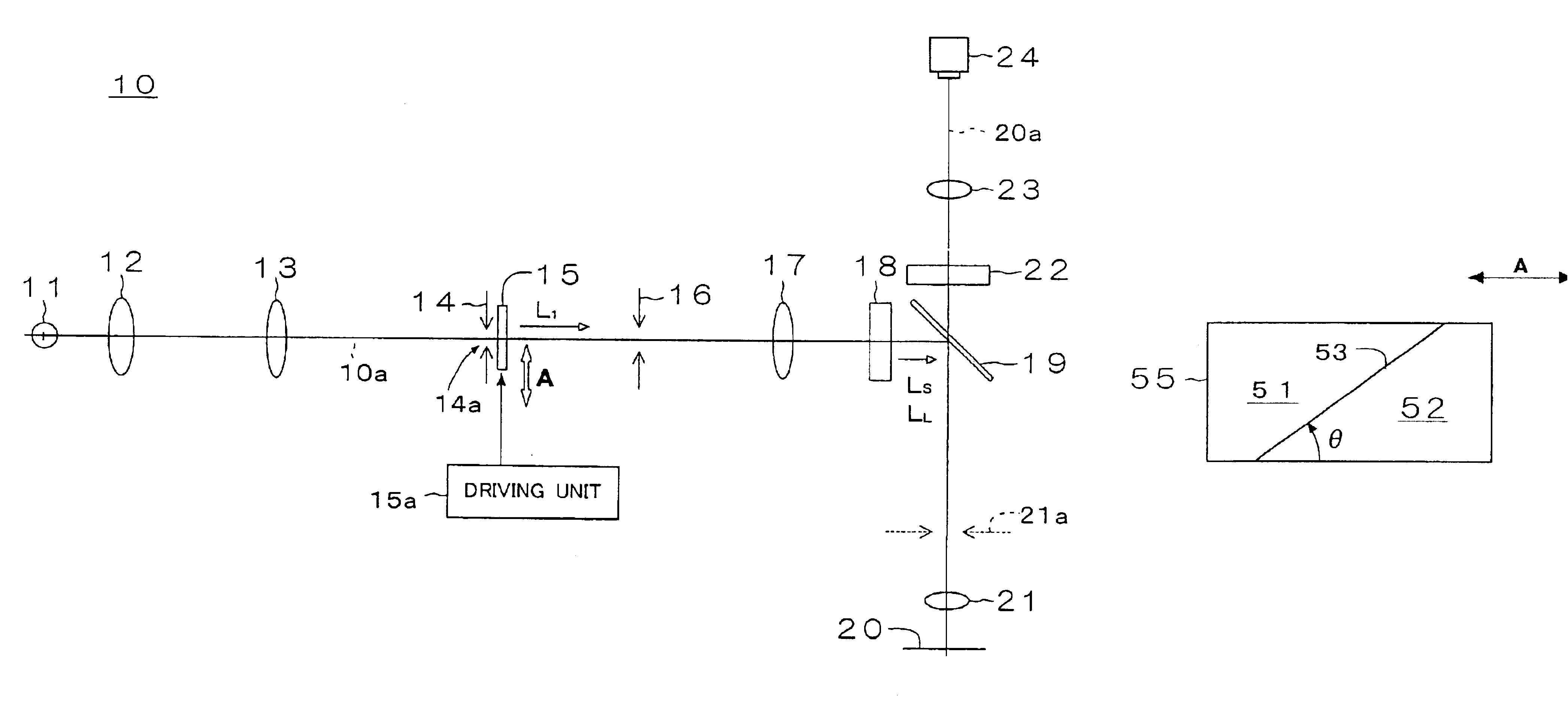
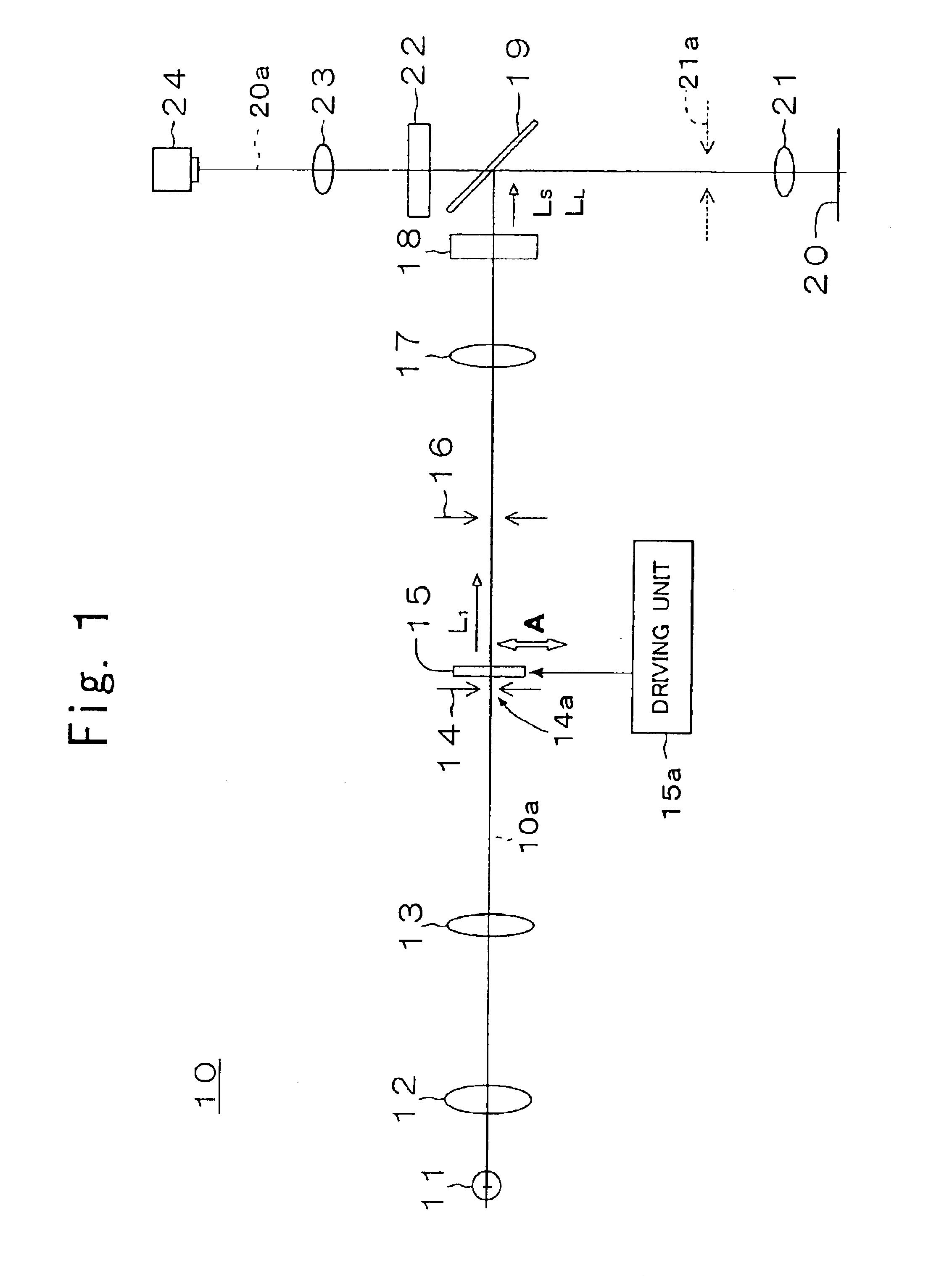
[0016]According to this epi-illumination apparatus, the sample can be excited by the illuminations in the plurality of narrow wavelength bands. In addition, balance in light intensity of the illuminations in the plurality of narrow wavelength bands can be adjusted easily by simply moving the filter in the direction orthogonal to the optical axis. The balance in light intensity of the illuminations in the plurality of narrow wavelength bands depends on the spectral transmission characteristics in the region of the filter on the optical axis.
[0023]As above, the epi-illumination apparatus for fluorescent observation according to the present invention can adjust the light intensities of a plurality of illuminations on a sample over a wide wavelength band continuously, and can be formed inexpensively. The fluorescence microscope according to the present invention can equalize the light intensities of fluorescence occurring from respective fluorescence materials of a sample for favorable fluorescent observation.

Problems solved by technology

Such a mixture of brighter images and darker images in the fluorescence image of the sample makes it difficult to obtain a picture suited for fluorescent observation.
In the foregoing method of rotating an interference filter, however, the spectrum of the illumination transmitted through the interference filter can only be shifted within a small range.
Thus, there has been the problem that the wavelength band allowing adjustments to the light intensities of the plurality of illuminations is narrow.
This means complicated operations and higher costs.
Moreover, in the foregoing method of switching interference filters, it is impossible to adjust the light intensities of the plurality of illuminations continuously.
A single excitation filter requires a plurality of interference filters, which cause an increase in cost.

Method used


Image

  • Epi-illumination apparatus for fluorescent observation and fluorescence microscope having the same
  • Epi-illumination apparatus for fluorescent observation and fluorescence microscope having the same
  • Epi-illumination apparatus for fluorescent observation and fluorescence microscope having the same

Examples


first embodiment

Modified Example of First Embodiment

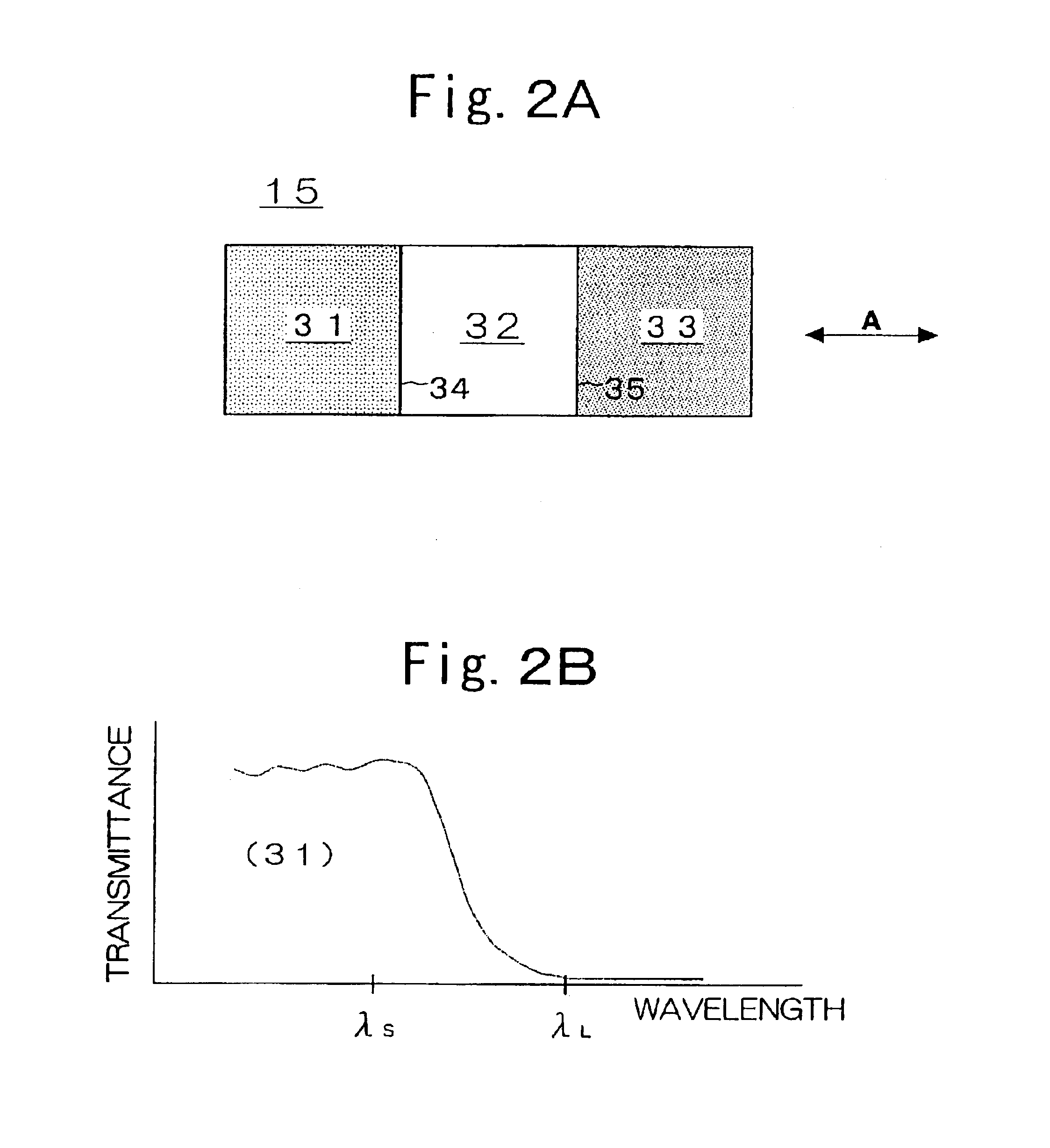
[0156]The foregoing embodiment has dealt with the case where the light intensity balance filter 15 has the three zones 31, 32, and 33 which are arranged along the one direction (A) as shown in FIG. 2(A). However, the present invention is not limited thereto. The number of zones of the light intensity balance filter may be two, four, or over.

[0157]For example, when the light intensity balance filter is composed of two zones, the possible combinations include: (1) a short wave transmission zone and a full transmission zone; (2) a long wave transmission zone and a full transmission zone; and (3) a short wave transmission zone and a long wave transmission zone.

[0158]In the case of (1) above, the balance in light intensity between the illuminations LS and LL can be adjusted by maintaining the short-wave illumination LS at its maximum light intensity and dimming the long-wave illumination LL. In the case of (2) above, the balance in light intensity betw...

second embodiment

Modified Example of Second Embodiment

[0221]The foregoing embodiment has dealt with the case where the opening 62a in the aperture stop 62 has a constant width (dimension with respect to the one direction (A)). However, as shown in FIGS. 15(A) and 16(A), the opening 62a may be varied in width with the optical axis 60a at its center. Such changes can also be made easily through manual operations using the driving unit 67 (FIG. 10) mentioned above.

[0222]In this case, as shown in FIGS. 15(B) and 16(B), the spectral width of the illumination Lo to be transmitted through the variable spectral filter 63 can be adjusted easily depending on the width of the opening 62a. The greater the width of the opening 62a is, the wider the spectral width of the illumination L0 is. Then, the light intensities of the two illuminations L1 and L2 for the sample 20 to be irradiated with can be increased or decreased simultaneously.

[0223]In the foregoing embodiment, a single variable spectral filter 63 is arr...


PUM


Abstract

An epi-illumination apparatus for fluorescent observation, adjusting light intensities of a plurality of illuminations on a sample over a wide wavelength band continuously and being configured inexpensively, and a fluorescence microscope having the same are provided. A light source, extracting means, an aperture stop, and a filter are arranged on a predetermined optical axis. The aperture stop is arranged on a plane generally conjugated with a pupil plane of an objective. The filter is placed near the aperture stop. The extracting means extracts a plurality of narrow wavelength bands from the wavelength band of the illumination emitted from the light source. The filter has regions of different spectral transmission characteristics to the narrow wavelength bands. The adjusting means for adjusting light intensities of transmitted light from the filter in the narrow wavelength bands independently by moving the filter in a direction orthogonal to the optical axis is provided.

Description

CROSS REFERENCE TO RELATED APPLICATIONS[0001]This application is based upon and claims the benefit of Japanese Patent Application No. 2002-164633, filed on Jun. 5, 2002, and Japanese Patent Application No. 2002-168386, filed on Jun. 10, 2002, the entire contents of which are incorporated herein by reference.BACKGROUND OF THE INVENTION[0002]1. Field of the Invention[0003]The present invention relates to an epi-illumination apparatus for fluorescent observation and a fluorescence microscope having the same. In particular, the present invention relates to an epi-illumination apparatus for fluorescent observation for illuminating a sample that is marked with a plurality of fluorescence materials, and a fluorescence microscope having the same.[0004]2. Description of the Related Art[0005]Conventionally, fluorescent observations of a sample marked with a plurality of fluorescence materials have been conducted by using a fluorescence microscope or the like. The plurality of fluorescence mat...

Claims


Application Information

Patent Timeline
Patent Type & Authority Patents(United States)
IPC IPC(8): G02B21/16G02B21/08G02B21/06
CPCG02B21/06G02B21/16G02B21/08
Inventor NIHOSHI, TOSHIAKIOKUGAWA, HISASHI
Owner NIKON CORP
Learn More