Method and apparatus for measuring and estimating optical signal to noise ratio in photonic networks

a photonic network and optical signal technology, applied in the direction of wavelength-division multiplex system, transmission monitoring, multiplex communication, etc., can solve the problem of complex and less tolerant transmission system, no longer simple operation for determining the cause of a distortion in the received signal

Inactive Publication Date: 2005-06-14
CIENA
View PDF9 Cites 20 Cited by
  • Summary
  • Abstract
  • Description
  • Claims
  • Application Information

AI Technical Summary

Benefits of technology

[0017]This rework enables the OSNR to be measured accurately at any site in the network, using calculations in which noise shaping of the nodes can be factored in to the calculation of OSNR. The noise shaping influence of the nodes is determined using analysis of the signals at amplifier sites upstream and downstream of the nodes.
[0023]Each node may also be provided with apparatus for measuring a Q value of the optical signal. The nodes will use transponders, for wavelength shifting, regeneration, or for reading header data, and the Q measurement circuit may be associated with these transponders. The network may then enable the Q value to be calculated at each amplifier site using the measured Q values at the nodes in combination with the signal to noise ratios for the amplifier sites and the node sites. This enables the Q value to be obtained at all locations in the network including the amplifier sites, without requiring opto-electronic conversion at the amplifier sites.

Problems solved by technology

Optical signals suffer degradation between the transmitter and receiver from such factors as noise, inter-symbol interference, fiber dispersion, non-linearity of the elements and transmission medium.
In the last decade, transmission rates of data signals have increased progressively, which has led to more complex and less tolerant transmission systems.
With various types of dispersion shifted fiber, dispersion compensating fiber and dispersion compensating elements that make up a given link, determining the cause of a distortion in the received signal is no longer a simple operation, especially in optical transmission systems with in-line optical amplifiers.
System performance degradation caused by noise and optical path distortions are also usually difficult to separate, making the performance evaluation complicated.
However, conventional optical signal to noise ratio measurements rely on the noise having constant slope.
However, it is difficult to achieve sufficient extinction on of the data signal when measuring the much smaller noise level, and the polarisation state of a signal will evolve over time.
These aspects make the process complicated and inaccurate.
This enables the noise to be measured at the channel frequency, but requires interruption of the data signal and can not therefore be used in live systems.
There will, however be a greatly increased error ratio in interpreting the zeros.
A problem arises that Q cannot be measured without opto-electric conversion circuitry, and cannot be measured at amplifier sites without providing additional circuitry.

Method used


Image

  • Method and apparatus for measuring and estimating optical signal to noise ratio in photonic networks
  • Method and apparatus for measuring and estimating optical signal to noise ratio in photonic networks
  • Method and apparatus for measuring and estimating optical signal to noise ratio in photonic networks

Examples


Embodiment Construction

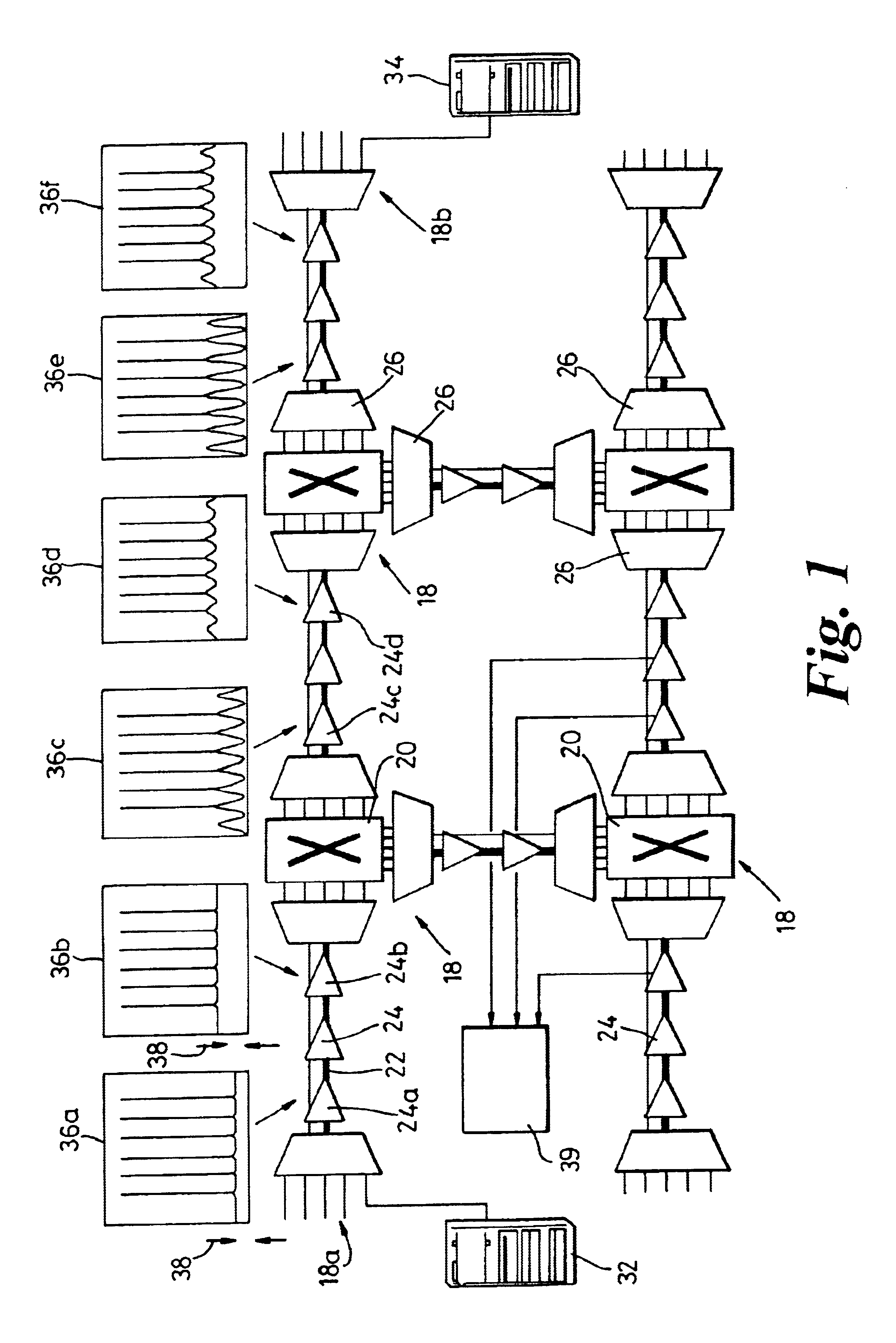
[0042]FIG. 1 shows a WDM optical communications network comprising a plurality of interconnected nodes 18, each node comprising an optical switching arrangement 20 for performing routing of signals across the network. The nodes are connected together by optical fibers 22 along which optical amplifiers 24 are placed. The fibers 22 carry WDM optical signals, and each node comprises multiplexing / demultiplexing units 26 which provide the channels of the WDM system on individual fibers to the switching arrangement 20. The switching arrangement may switch individual channels or else bands of channels.

[0043]The network enables equipment 32 at a source node 18a (not shown in full) to communicate with equipment 34 at a destination node 18b (not shown in full). The equipment 32, 34 is any device which provides optical signals for transmission over the network or which is provided for receiving signals from the network.

[0044]Each node 18 may be able to perform a regeneration function for some ...


PUM


Abstract

A WDM optical network comprising a plurality of nodes has a first apparatus for optical analysis at the site of a first optical amplifier upstream of the first node, a second apparatus for optical analysis at the site of a second optical amplifier at the downstream output of the first node, and a third apparatus for optical analysis at the site of a third optical amplifier further downstream of the first node, where knowledge of the optical sin to noise ratio (OSNR) is desired. The first, second and third apparatus are for measuring the signal level at frequencies both at and in-between the channel frequencies. The signal levels at the channel frequencies and between the channel frequencies at the first, second and third apparatus are used to derive the OSNR at the third apparatus. This enables the OSNR to be measured accurately at any site in the network, using calculations in which noise shaping of the nodes can be factored in to the calculation of OSNR.

Description

FIELD OF THE INVENTION[0001]This invention relates to performance analysis in optical systems, and particularly to the determination of optical signal to noise ratio at different locations within an optical communications network.BACKGROUND OF THE INVENTION[0002]Optical signals suffer degradation between the transmitter and receiver from such factors as noise, inter-symbol interference, fiber dispersion, non-linearity of the elements and transmission medium. In addition, in amplified wavelength division multiplexed (WDM) systems, the transmission characteristics vary from one channel to another due to the non-flat gain and noise profile of erbium-doped fiber amplifiers (EDFAs).[0003]Distortion is defined as any inaccurate replication of a signal transmitted over a communication link, and could originate in any network element (NE) along the link. It can be measured by assessing the difference between the wave shape of the original signal and that of the signal at the network element...

Claims


Application Information

Patent Timeline
Patent Type & Authority Patents(United States)
IPC IPC(8): H04J14/02H04B10/08
CPCH04J14/02
Inventor HEATH, RICHARD WANSLOW, PETER J
Owner CIENA
Why Eureka
Try Eureka